Universal Serial Bus (USB)
USB has become the standard connection type for peripherals like printers, scanners, keyboards, mice and digital cameras. It has largely replaced other types of peripheral interface, including the 9-pin and 25-pin serial ports, and the parallel printer port. USB embodies a plug-and-play approach that allows peripheral devices to be connected to the computer, configured and used, and disconnected again without ever turning off the computer.
Host controllers built into the motherboard of a personal computer or USB hub manage any attached USB peripherals, relieving the CPU of having to do so and thereby greatly improving system performance. Virtually all operating systems now fully support USB version 2.0 and its predecessors.

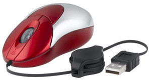
A USB mouse
The USB specifications are overseen by the USB Implementers Forum (USB-IF), an industry standards body whose current membership includes Microsoft, NEC, Ericsson, Hewlett-Packard, Intel and LSI. The USB 1.0 specification was introduced in 1996, but was not widely adopted immediately due to various problems. Most of the problems were fixed in version 1.1, which was released in 1998 and offered a low-speed data transfer rate of 1.5 Mbps, and a full-speed data transfer rate of 12 Mbps.
The low-speed rate was primarily provided to accommodate low-bandwidth human interface devices such as the keyboard and mouse. The USB 2.0 specification was released in 2000, and although backwardly compatible with previous versions offered a new hi-speed data rate of 480 Mbps. 2008 saw the release of the USB 3.0 specification, which introduces the so-called SuperSpeed data rate with a nominal maximum speed of 4.8 Gbps. The first USB 3.0 consumer products became available during 2010.
USB connectors and sockets
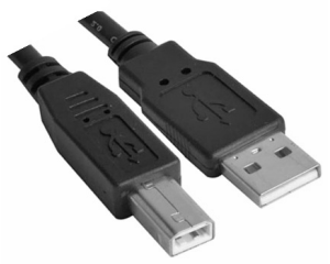
The standard USB connectors are designed to require only moderate insertion force, but due to their design they cannot be plugged in upside down. For larger peripherals such as printers and scanners, a Type A connector is used at the end of the cable that attaches to the computer (the "upstream" connection), while a Type B connector is used at the end that attaches to the peripheral device (the "downstream" connection).
Connectors are designed in such a way that when they are plugged in the external metal sheath, which is typically connected to system ground, makes contact with its counterpart in the socket before any of the four contacts within the connector (each of which corresponds to one of the signal or power wires in the cable) make electrical contact. This arrangement eliminates the possibility of damage due to static charge, which will be dissipated to earth before the connector is fully inserted.
The design of the connector enclosure also affords a degree of protection to the signals travelling through the connector – the only part of the cable where the wires are (of necessity) in parallel. The most common connector types are shown below.

Common USB connector configurations
The Mini-A, Mini-B, Micro-AB and Micro B connectors are typically used for smaller devices such as PDAs, mobile phones and digital cameras. The Mini-A and Mini-B connectors are approximately 7mm wide and 3mm thick, while the (newer) Micro-AB and Micro-B connectors are of a similar width but only about half as thick, enabling them to be used for even smaller portable devices, and are designed to cope with a considerably larger number of connect-disconnect cycles.
USB 3.0 connectors are intended to provide some backward compatibility with earlier versions, although the form factor has been modified to accommodate the additional pins required, and will inevitably create some incompatibilities. Standard USB 3.0 Type-A connectors have heads that extend beyond and slightly above the legacy connectors, and the socket is modified to accommodate the extension. A similar situation applies to the Type-B connectors. In short, standard USB 2.0 cables should still fit into USB 3.0 sockets, but the reverse will not be true.

Standard USB Type-A (right)and Type-B (left) connectors

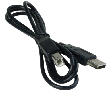
A standard USB 2.0 cable
Cables
The maximum length of a standard USB cable for USB 2.0 or earlier is 5 metres, due to the specified maximum round-trip delay of 1.5 µs. USB data cables employ twisted-pairs to reduce crosstalk and noise. Since the number of USB hubs that may be connected in series is 5, there could be up to 30 metres between a USB host and a device. Due to the significantly higher data rates promised for USB 3.0, it is generally considered that cable lengths for data cables should not exceed 3 metres. Technical details of the wiring and pin designations for USB 1.x and 2.0 cables are shown below.
| Pin No. | Name | Colour Code | Description |
|---|---|---|---|
| 1 | VCC | Red | +5V supply voltage |
| 2 | D- | White | Data- |
| 3 | D+ | Green | Data+ |
| 4 | GND | Black | Ground (standard cable) |
| 4 | ID | N/A | Identifies cable type as Micro-A (connected to ground) or Micro-B (not connected) |
| 5 | GND | Black | Ground (Mini/Micro connectors) |
For USB 1.x or 2.0, communication is half-duplex and the direction in which data is flowing at any given time is determined by the host. USB 3.0 cables employ an additional four wires (two shielded twisted pairs) to carry full-duplex SuperSpeed data.
USB class codes
USB devices are classified according to their functionality, and device drivers can nominally be selected for a device based on that functionality. The class information is stored in three separate code bytes referred to here as the Base Class, SubClass, and Protocol. The table below shows some of the currently defined Base Class values, together with a brief description of the types of devices they refer to.
| Base class | Device type |
|---|---|
| 01h | Audio |
| 02h | Communication |
| 03h | Human Interface Device (HID) |
| 05h | Physical |
| 06h | Still Imaging |
| 07h | Printer |
| 08h | Mass Storage |
| 09h | Hub |
| 0Ah | CDC-Data |
| 0Bh | Smart Card |
| 0Dh | Content Security |
| 0Eh | Video |
| 0Fh | Personal Healthcare |
| DCh | Diagnostic |
| E0h | Wireless Controller |
| EFh | Miscellaneous |
| FEh | Application Specific |
| FFh | Vendor Specific |
USB networks
A USB system typically consists of a host (usually a personal computer or laptop computer), a host controller (usually built into the computer’s motherboard), and two or more USB ports, to which various peripheral devices may be attached. The devices that can be attached to a USB port include USB hubs, which provide additional ports and can be used to expand the number of USB devices that can be attached to a single computer or other USB host in a tiered star topology.
Additional hubs can be included at each tier, and a total of up to five tiers are allowed. A USB host may have more than one host controller, with up to 127 USB devices (including hubs) attached to a single host controller. Each host controller incorporates a single high-level hub known as the root hub.
A USB device may incorporate a number of device functions. A webcam primarily provides a video device function, for example, but will often incorporate a built-in microphone (an audio device function). In compound devices such as this, each logical device is assigned a unique address by the host. When a device is connected to a USB host, an enumeration process is started during which the host determines what type of device it is dealing with, and the speed at which it can send and receive data. The device is then assigned a unique 7-bit address, and the appropriate device drivers are loaded.
When the host is first powered up, the enumeration process is repeated for each connected device. USB 2.0 devices must wait for the host controller to initiate operations. USB 3.0 allows devices to request services from the host controller, and a USB host has two separate host controllers – one for USB 3.0 devices, and one to support legacy devices.
During the enumeration process, the host also determines the mode of communication required for each attached device. A mouse or keyboard will need to send only relatively small amounts of data in an asynchronous fashion, and will thus employ the interrupt mode. A printer will need to receive sizable blocks of information and therefore uses the bulk transfer mode.
For other devices (such as speakers) the need to receive a constant stream of data is far greater than the need for error-free data. The isochronous mode allows data transfer between the device and the host to occur in real time, and does not provide error correction. Bandwidth is allocated as 1,500 byte frames, and a new frame is generated every millisecond. Within each frame, space is available for isochronous, interrupt, and bulk transfer data.
Devices that use the isochronous and interrupt modes may be allocated up to 90% of the available bandwidth (a total of 480 Mbps is shared between all the devices attached to a host for USB 2.0). The remaining bandwidth (a minimum of 10%) is reserved for control data and devices that use the bulk transfer mode.
Power
While some devices (such as printers) require relatively large amounts of power and therefore have their own power supply, some smaller devices need relatively little power and can draw the required current from the host device, greatly simplifying their design and reducing their cost.
A USB host can provide up to 500mA of current, and the USB 1.x and 2.0 specifications provide for a +5V supply on the VCC pin. Power is allocated to individual devices as required on the basis of unit loads. A unit load is 100mA for USB 2.0 or 150mA for USB 3.0. A maximum of 5 unit loads (500mA) can be drawn from a single port for USB 2.0.
USB 3.0 raises the maximum current that can be drawn to 6 unit loads (900mA). Low-power devices draw only 1 unit load and have an operating voltage of 4.4V (USB 2.0) or 4V (USB 3.0). High-power devices draw the maximum number of unit loads supported. A powered hub is capable of supplying the maximum number of unit loads to any device connected to it.
