Kirchhoff's Laws
Overview
Kirchhoff's laws reveal a unique algebraic relationship between current, voltage, and resistance in electrical circuits that is vital to our understanding of electrical circuit analysis. Many circuits are very complex, with multiple power sources and branches, and cannot be solved using Ohm's Law alone. Through experimentation in 1857 the German physicist Gustav Kirchhoff developed methods to solve complex circuits, known today as Kirchhoff's voltage and current laws.
Kirchhoff's Current Law:
At any junction in an electric circuit the total current flowing towards that junction is equal to the total current flowing away from the junction.
Kirchhoff's Voltage Law:
In any closed loop in a network, the algebraic sum of the voltage drops (i.e. products of current and resistance) taken around the loop is equal to the resultant electromotive force acting in that loop.
These laws may seem obvious based on what we already know about circuit theory, but they are powerful tools in the analysis of complex circuits. Kirchhoff's laws can be related to the conservation of energy and charge. Consider a circuit with one load and one source. Since the load consumes all of the power provided by the source, energy and charge are conserved. Since voltage and current can be related to energy and charge, then Kirchhoff's laws appear to be simply restating the laws governing energy and charge conservation. The mathematics involved becomes more difficult, however, as the circuits become more complex. Kirchhoff's theories provide the basis of an algebraic approach to circuit analysis that Ohm's law alone does not.
Kirchhoff's Current Law
This fundamental law results from the conservation of charge. It applies to a junction (or node) in a circuit - a point in the circuit where charge has several possible paths to travel. In the following diagram, I A is the only current flowing into the node. However, there are three paths for current to leave the node, and these current are represented by I B, I C, and I D.
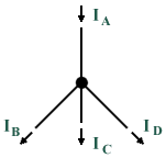
A node (or junction) in a circuit
Once charge has entered the node, it has nowhere to go except to leave (this is known as conservation of charge). The total charge flowing into a node must be the same as the total charge flowing out of the node. So,
I A = I B + I C + I D
Bringing everything to the left side of the above equation, we get:
I A - (I B + I C + I D) = 0
Then, the sum of all the currents is zero. This can be generalised as follows:
| Σ | I = 0 |
Note that the convention assumed here is that currents flowing into the node are taken to be positive, and currents flowing out of the node are taken to be negative. It should not really matter which direction you choose to be the positive or negative current, as long as you are consistent.
Kirchhoff's Voltage Law
The voltage law gives the relationship between the voltage drops around any closed loop in a circuit and the voltage sources in that loop. The total of these two quantities is always equal. Stating this as an equation, we get:
E 1 + E 2 + E 3 + . . . = I 1 R 1 + I 2 R 2 + I 3 R 3 + . . .
or . . .
| Σ | E = | Σ | IR |
Kirchhoff's voltage law can be applied only to closed loops. A closed loop must meet two conditions:
- It must have one or more voltage sources
- There must have a complete path for current to flow from any point in the loop, around the loop, and back to that point
In a simple series circuit, the sum of the voltage drops around the circuit is equal to the applied voltage. This is Kirchhoff's voltage law applied to the simplest case, i.e. there is only one loop and one voltage source. Kirchhoff's Voltage Law is a result of the electrostatic field being conservative. It states that the total voltage around a closed loop must sum to zero, so:
| Σ | V = 0 |
In the following diagram, the total voltage around Loop 1 should sum to zero, as should the total voltage around Loop 2. Furthermore, the voltage drops in the loop comprising the outer part of the circuit (path A-B-C-D-A) should also sum to zero. The convention normally adopted is that a potential gain (such as a voltage source) is taken to be positive. A potential loss (such as the voltage drop across a resistor) will be taken to be negative.
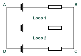
Around a closed loop, the total voltage should be zero
In the diagram below, the voltage drops across the resistors are denoted using arrows, with the arrowheads pointing towards the higher voltage. For example, in resistor R1 conventional current flows from left to right through it. As the current travels through the resistor, the voltage decreases, creating a lower voltage on the right hand side. Note that there are two voltage sources in the circuit, E1 and E2. Not that the two sources supply current in opposing directions, although the overall conventional current flow through the circuit is in a clockwise direction.
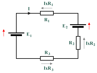
The voltage drops as current passes through a resistor
We must assume a convention to determine whether a voltage is considered positive or negative. It does not matter which convention is used, but the normal method is to say that clockwise arrows are positive and anticlockwise arrows are negative, therefore:
E 1 - IR 1 - E 2 - IR 2 - IR 3 = 0
or . . .
E 1 - E 2 = IR 1 + IR 2 + IR 3
The following circuit includes three resistors of equal resistance in series with a 9 V battery. Using what you have learned so far, write down the voltage drops across each resistor (denoted by V 1, V 2 and V 3) and the current you would expect to measure at the points in the circuit indicated by I 1, I 2, I 3 and I 4 (hint: would you expect the currents to be different?). Once you have recorded the expected values, check your answers by hovering over the labels on the diagram. If you have circuit simulation software, use it to create the circuit shown and verify the results. A sample screenshot is shown below the diagram.
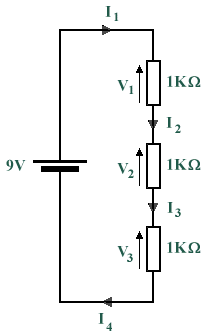
Simple circuit with three resistors in series
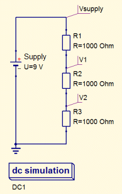
Example of a circuit simulation using QUCS
The circuit below also includes three resistors of equal resistance and a 9 V battery, but this time they are connected in parallel. As before, write down the voltage drops across each resistor (denoted by V 1, V 2 and V 3). Note that the current flow around the circuit will be much greater for this arrangement of resistors because the resistors are in parallel. The overall circuit resistance will actually be less than that of the resistor with the lowest value (we will be examining the behaviour of resistor networks more closely in a later section). Once you have recorded the expected values, check your answers by hovering over the labels on the diagram. If you have circuit simulation software, use it to create the circuit shown and verify the results.
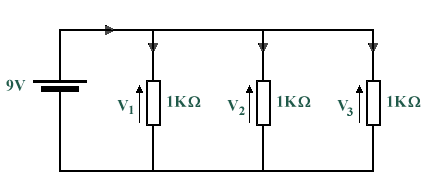
Simple circuit with three resistors in parallel
Problems
-
In the diagram below, circuit nodes A through E each have one or more current flows into and out of them. You have been given some of the current values, and are required to apply Kirchhoff's current law to determine the value of the unknown currents I 1 through I 5. A solution can be seen by clicking on the "Answers to problems" link at the bottom of this page.
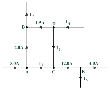
Find the unknown currents entering or leaving each node
-
In the diagram below, four voltage sources are connected in series with four resistors. The value of one of the voltage sources, E, is unknown. Using what you know about Kirchhoff's voltage law, determine the voltage being supplied by E. A solution can be seen by clicking on the "Answers to problems" link at the bottom of this page.
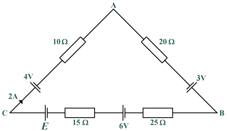
Find the value of E