Resistor Networks
Circuits consisting of just one voltage source and one load resistance are very simple to analyse, but they are rarely found in practical applications. Usually, we find circuits where a number of components are connected together. There are two ways in which circuit components can be connected - in series and in parallel. Using Kirchhoff's voltage and current laws, we can determine what happens when we place resistors into a circuit in series and in parallel, or even in circuits that involve a complex arrangement of resistors in series and in parallel with each other. We often collectively refer to such configurations as resistor networks. Consider a network of resistors in which resistor R1 may be connected in series or parallel with resistor R2, resistor R3 may be connected in series or parallel with the network consisting of R1 and R2, and so on. The resistance of two or more resistors in series is given by:
RTOTAL = R1 + R2 + R3 . . .
and of two or more resistors in parallel by:
| RTOTAL = | 1 | ||||||||
|
When calculating the total resistance of multiple resistors in parallel, a quick way to check whether your answer is at least approximately correct is that it should be less than the value of the smallest resistor. Essentially, where complex networks of resistors are to be analysed, the combined resistance of a group of resistors in parallel can be calculated and then treated as a single resistance value. This resistance value can then be dealt with as if belonging to a single resistor in series with other circuit elements. Note that, for any two resistors to be in series, exactly the same current must be flowing through each resistor at any given time, while the total voltage drop across the two resistors will be the sum of the voltage drops across each individual resistor. For two (or more) resistors to be in parallel on the other hand, it is the voltage drop across each resistor that must be the same, and the total current flow through the resistors will be the sum of the current flow through each individual resistor.
An alternative formula for obtaining the equivalent resistance for two resistors in parallel is shown below. Note, however, that this formula can only be applied to two resistors in parallel. For three or more resistors in parallel, the formula shown above must be used.
| RTOTAL = | R1 × R2 |
| R1 + R2 |
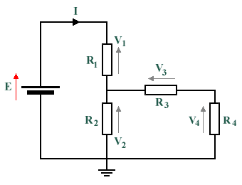
Consider the simple resistor network below:

A simple resistor network
The questions to be answered when analysing a circuit centre on determining which circuit elements are in series, and which are in parallel. Remember that in order for two circuit elements to be in series with each other, the same current must flow through both. We can clearly see from the diagram that the battery is in series with resistor R1, and that resistors R3 and R4 are in series with each other. Resistors R1 and R2 are not in series, because some of the current flowing through resistor R1 also flows through resistor R3. Resistor R2 is in parallel with the series resistor combination consisting of R3 and R4, and resistor R1 is in series with the parallel network formed by resistors R2, R3 and R4.
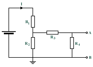
We have redrawn the circuit below to include terminals A and B. Any load connected across these terminals would be in parallel with resistor R4, so the current passing through R3 would be divided between resistor R4 and the load, which would also have a resistance). One consequence of this would be that resistor R4 would no longer be in series with resistor R3, because some of the current from R3 would now pass through the load. The proportion of the current from R3 that would flow through resistor R4 and through the load will obviously depend on the resistance values of each of these elements.

What is the effect of adding a load resistance across terminals A and B?
Problems
- The voltages dropped across three resistors (R1, R2 and R3) connected in series are 5 V, 7 V and 10 V respectively. The supply current is 2 A. Calculate the supply voltage and the values of the three resistors.
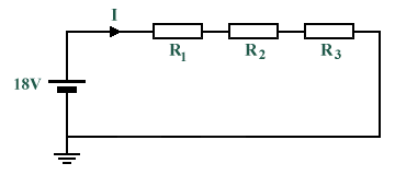
- For the circuit shown below, given that the voltage dropped across R2 is 5 V and that the voltage dropped across R3 is 3 V, determine the value of the voltage dropped across R1. If the total circuit resistance is 36 Ω, calculate the supply current and the resistor values.

- Two resistors are connected in series across an 18 V supply with a current of 5 A flowing through the circuit. If one of the resistors (R1) has a value of 2.4 Ω, determine the value of the other resistor (R2), and the voltage dropped across R1.
- Imagine that you have a 100 Ω resistor (R1). You want to add a resistor (R2) in series with R1 in order to limit the current to 0.5 amps when 110 volts is placed across the two resistors in series. How much resistance should you use?
- Two resistors (R1 and R2) of value 4 Ω and 12 Ω are connected in parallel across a 9 V battery. Calculate the resistance of the parallel branch, the supply current, and the current flowing through each resistor.
- Find the total resistance between terminals A and B of the circuit of the circuit shown below.

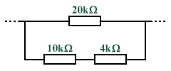
- What is the equivalent resistance for this resistor combination?

- Resistors of value 20 Ω, 20 Ω and 30 Ω are connected in parallel. Determine the value of the series resistance that must be added to the parallel combination to obtain a total resistance of 10 Ω. If the completed circuit dissipates a power of 0.36 kW, find the current flowing.
