| Author: | |
| Website: | |
| Page title: | |
| URL: | |
| Published: | |
| Last revised: | |
| Accessed: |
Like most of the quantities we will talk about in this section, length is one of the base quantities defined by the International System of Units. The internationally agreed base unit for length is the metre. Commonly encountered multiples and sub-multiples of length include the kilometre (one kilometre is equal to one thousand metres) and the millimetre (one millimetre is equal to one thousandth of a metre). You have no doubt used a ruler, a measuring tape, a metre rule or a yardstick to measure the length of various items. These common measuring devices (the generic term for which is measure) are also sometimes used by scientists, where appropriate, for measuring length. Typically, this kind of measure is marked (graduated) with major intervals in centimetres and minor intervals in millimetres. With a metre rule, therefore, we can measure the length of an item up to one metre in length, to the nearest millimetre.
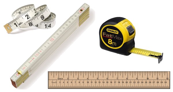
A selection of tools commonly used to measure length
For many purposes, a graduated measure of the kind illustrated above is perfectly adequate. Obviously, care must be taken when measuring. The measure should be carefully positioned so as to ensure that the first mark on the measure (i.e. the mark representing zero) is aligned with one end of the length being measured. You are then looking for the mark on the measure that most closely aligns with the other end of the length being measured. Note that the eye should be vertically above the measure and the object being measured in order to minimize the possibility of parallax errors. If you don't know what a parallax error is, try looking at an old-fashioned analogue clock (i.e. one with hands) from different angles. You will see that, because the hands of the clock are not completely flush with the face of the clock, they can appear to point to slightly different points on the clock face, depending on your position relative to the clock.
Another point to note here is that the resolution of the measure is determined by the smallest distance between minor graduations. In the case of the type of measure illustrated above, the smallest distance between graduations is normally one millimetre. A more formal definition of resolution, and one that can be applied to measuring tools and instruments of all kinds, is the smallest change in input that can be detected at the output. In the case of our millimetre-graduated measure, a change in the length being measured (i.e. a change of input) of one millimetre will be easily detected, so long as we exercise due care and attention when making measurements, and have reasonably good eyesight (or a decent pair of reading glasses). The output in this case will be the position of the mark on the measure that aligns with the end of the object being measured, as observed and recorded by the person making the measurement.
When more accurate measurements of length are required, or when the length being measured cannot easily be measured with the type of measure discussed above, we need to use a different type of measuring instrument. One such instrument is called a vernier caliper. A typical vernier caliper is illustrated below. As you can see, it has a large pair of jaws for taking external measurements, and a much smaller pair of jaws that can be used for internal measurements. In addition to the standard graduated scale found on other types of measuring tool, the vernier caliper has an additional scale called a vernier scale, after the French mathematician Pierre Vernier who invented it in 1631. The vernier scale is designed to allow the user to detect much smaller variances in length than would be possible using a standard measure. A vernier caliper is typically used to measure the outside diameter of a rod or hollow pipe. In the case of a hollow pipe, it can also be used to measure the inside diameter.
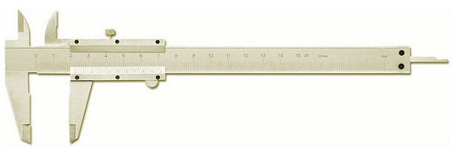
A typical vernier caliper
The graphic below shows a simplified view of the vernier caliper. The main scale is on the body of the caliper, and is marked off in centimetres, with each minor interval representing one millimetre. The vernier scale is on the sliding part of the vernier caliper, and is also apparently marked off in millimetres. However, closer examination will reveal that each minor interval on the vernier scale is in fact fractionally less than one millimeter. In our example, that fraction is one-tenth of a millimetre (0.1 mm). You will notice that, because the jaws of the vernier caliper are closed in the illustration, the zero mark on both scales is aligned. The remaining marks on the vernier scale are progressively out of step with the corresponding marks on the main scale. Although this may seem rather odd, it actually allows us to measure the outer dimension of an object (such as a steel bar or a copper pipe, for example) to a precision of one tenth of a millimetre.
A simplified partial view of the vernier caliper with jaws closed
The next illustration (below) demonstrates the principle. We are using the vernier caliper to measure the diameter of a thin-walled aluminium tube. The tube actually has an outer diameter of (approximately) five-point-seven millimetres (5.7 mm). Let's assume that we either don't know this, or that we are trying to verify it. If you look at the zero mark on the vernier scale, you will see that it lies somewhere between the five millimetre mark and the six millimetre mark on the main scale. Our tube must therefore be between five and six millimetres in diameter, and just from looking at it I would say it was nearer six millimetres than five. To get a more precise figure, however, we need to look at the vernier scale.
Using the vernier caliper to measure the diameter of a tube
The zero mark on the vernier scale, as we have said, lies somewhere between the five millimetre mark and the six millimetre mark on the main scale. If we look closely, we can see that it lies significantly closer to the six millimetre mark, at about two thirds of the distance between the two. Remember that, because it will have a bearing on our final reading.
Let's now turn our attention to the vernier scale itself. The value of each interval on the vernier scale is usually shown somewhere on the scale. If not, you can determine its value by dividing the smallest interval on the main scale (in this case 1 mm) by the number of units on the vernier scale (which is 50), so each interval represents an offset of 1/50 mm, or 0.02 mm.
What we need to look for here is a mark on the vernier scale that is approximately two thirds of the way along the vernier scale, and that aligns exactly with a mark on the main scale. This will give us the number of units that we must add to five millimetres in order to give us the exact measurement we require (remember that each unit on the vernier scale is worth 0.02 mm).
If you look carefully, you will see that this alignment occurs at the thirty-seventh interval on the vernier scale (we have shown the alignment using a red arrow on the illustration). This means that the outside diameter of our tube is 5 mm plus 37 × 0.02 mm, or 5.74 mm, which confirms the (approximate) dimension we were given above (many thanks to Joel Pomerleau for pointing out the errors in the original version of this description).
The micrometer is another device that can be used to measure length with a high degree of precision. As with the vernier caliper, the distances involved are relatively small. The first ever micrometric screw, as it was called, was invented by the English astronomer, mathematician and instrument-maker William Gascoigne (1612-1644) as an enhancement of the vernier scale. It was first used with a telescope to more accurately measure the apparent size (or angular diameter) of objects in the night sky such as the stars and planets, and the angular distances between them. By far the most common type of micrometer takes the form of a caliper, like the one shown below. The earliest known example of such a device was developed by the French inventor Jean Laurent-Palmer (about whom very little else seems to be known) in 1848. The device typically consists of a G-shaped frame, the "leg" of which incorporates a scale that can be used to read measurements.
A typical caliper-type micrometer
A calibrated screw is housed inside the barrel of the micrometer, which is surrounded by an outer cylinder called the sleeve. Another cylindrical component, called the thimble, fits over the sleeve. Turning the thimble clockwise causes the screw within the barrel to advance, while turning it anti-clockwise causes the screw to retreat. As the screw is turned through one complete rotation, it advances or retreats by a distance equivalent to its pitch (the pitch is the distance between the ridges of the helical screw thread, as measured parallel to the axis of the screw). The pitch (also sometimes called the lead) of the screw is typically 0.5 millimetres. The screw is attached to a (usually) flat-faced circular metal bar called the spindle. When the screw advances, it pushes the spindle towards a short, flat-faced circular metal bar called the anvil, which is attached to the opposite side of the G-shaped frame. The object to be measured is placed between the face of the spindle and the face of the anvil, and the screw is turned until the object is lightly held between the two faces.
The distance between the faces of the spindle will be the measurement we are looking for (in the illustration above, this is the diameter of a hollow pipe). It can be determined by reading both the scale on the sleeve and the scale on the thimble. The scale on the sleeve of the micrometer is typically marked at half-millimetre intervals. Whichever of these markings is closest to the front edge of the thimble (and still visible) will give us the measurement we seek to the nearest half-millimetre. The markings on the thimble tell us what proportion of a full turn the screw has actually made. On the caliper-type micrometer shown above, the scale on the thimble is divided into fifty (50) equally spaced intervals. Given that the pitch (or lead) of the screw is half a millimetre (0.5 mm), then each interval on the thimble represents one hundredth of a millimetre (0.01 mm). Let's take a closer look at the scales.

The zero mark on the thimble is aligned with the horizontal line on the sleeve
As you can see from the illustration above, the horizontal line on the sleeve of the micrometer lines up with the zero mark on the thimble. This means that the screw has just completed one complete turn and is about to start another. Since the thimble is clearly significantly past the fifteen-and-a-half millimetre mark on the sleeve, we can safely assume that it is sitting directly on the sixteen millimetre mark, which means that our tube is exactly sixteen millimetres (16 mm) in diameter. Some caliper-type micrometers additionally have a vernier scale on the sleeve, allowing measurements to be made with a precision of (typically) one thousandth of a millimetre (0.001 mm).
Using a micrometer requires a certain amount of care if accurate measurements are to be made. A common mistake is to over-tighten the screw, which can give an inaccurate measurement due to distortion of the material being measured, or over-tightening of the screw threads themselves. Some micrometers incorporate a ratchet mechanism that prevents the screw being over-tightened. Another consideration is the environment in which the micrometer is used. Because the frame of the micrometer is made of metal, it is subject to thermal expansion and contraction. The accuracy of the micrometer is therefore only guaranteed within a relatively narrow range of temperatures. Most micrometers are designed to give accurate measurements at around twenty degrees centigrade (i.e. room temperature). The frame of the micrometer is typically a rigid metal casting, which reduces the chances of it bending or flexing when in use. It will also have a relatively high thermal mass, which reduces the heating effects of being handled.