A Brief History of Navigational Instruments
Overview
It is easy enough to find your way around your home, your local neighborhood, or even your home town or city, but what if you need to go further afield? Suppose you are traversing a desert or an ocean with no familiar landmarks to guide you. It is very easy to get lost. Travelling merchants and explorers have faced these navigational challenges for thousands of years, and have developed numerous means of overcoming them. Since the dawn of history, mankind has used the Sun - the most predictable object in the sky - to determine the time of day and establish direction. Over many millennia, we have acquired knowledge about the positions occupied in the night sky by the Moon, stars and planets, and have used that knowledge for navigation. The following sections take a brief look at some of the instruments and technologies man has used to acquire such information, and to find their way around the globe.
The Compass
Prior to the invention of the compass, navigators could establish their position and direction of travel by looking at familiar landmarks, or by reference to the Sun and other celestial objects. If a ship was out of sight of land and beset by adverse weather conditions, navigation became virtually impossible.
The earliest compass is thought to have been invented in China as early as the third century BCE. These early direction-finding devices were made from lodestone (also known as magnetite), a naturally occurring form of iron ore with magnetic properties. Essentially, a piece of lodestone has its own magnetic field so that, when allowed to rotate freely around its axis, it will align its own magnetic field with that of the Earth. Thus, from the observer's point of view, the lodestone would always appear to "point" in the same direction.
It would be nearly a thousand years, however, before these seemingly magical properties were widely used for navigation. Instead, they were used for telling fortunes, or for determining the direction in which a new building should face in order to ensure the inhabitants enjoyed long life and prosperity. This is in keeping with the ancient Chinese art of Feng Shui, the goal of which is to achieve harmony with the invisible forces around us.
Early versions of the compass employed a pointer made from a piece of lodestone, often carved into the shape of a spoon or ladle, as shown in the illustration below. The pointer was typically placed on a square base plate made of bronze, engraved around its edges with the points of the compass and the major constellations. The spoon was allowed to rotate freely, and would always come to rest with its handle pointing towards the magnetic South Pole.
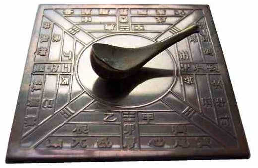
A replica of a Han Dynasty Chinese compass (www.grand-illusions.com)
The first compasses to be used for navigational purposes are believed to have appeared in China during the eleventh century CE, and typically employed magnetized iron needles suspended on a small piece of wood floating in a bowl of water. The Chinese had discovered at some point that rubbing an iron needle in a particular direction with a lodestone gave the needle the same magnetic properties possessed by the lodestone. Because the resulting magnetic field was not permanent, a piece of lodestone was carried by early navigators, and used as and when required in order to restore the compass needle's magnetic field.
Although it is uncertain exactly when the compass made its first appearance in Europe, there are numerous references to its use in the Mediterranean and elsewhere from the twelfth century onwards. Descriptions of the most common type of compass used by European navigators suggest that it was similar in design to that used by Chinese navigators, i.e. a magnetized needle floating in a bowl of water. From the evidence available, it seems likely that the compass was brought to Europe from China by Arab traders.
By about 1300 CE the compass had developed into the kind of instrument we are familiar with today. A typical mariner's compass (sometimes called a dry compass) consisted of a small box with a glass cover containing a freely rotating compass needle mounted on a pin. A compass card (also known as a compass rose or wind rose), marked with the four cardinal points (north, south, east and west), was glued to the top of the needle. The compass would occupy a fixed position in relation to the keel of the ship. This meant that, as the ship changed direction, the compass card would turn to indicate its current heading.
Later developments included the suspension of the needle above a fixed compass card - an innovation thought to have occurred in the early fourteenth century CE and often credited to the Italian mariner and inventor Flavio Gioja (although details of his life, and even whether he actually existed, are disputed). A gimbal mounting was also introduced to keep the compass needle relatively level in rough seas. This was intended to ensure that the needle could always rotate freely by preventing it from grounding itself on the compass housing.
By the end of the seventeenth century, the dry mariner's compass had largely been superseded by the liquid compass, in which the body of the compass is filled with a clear liquid in order to dampen the movement of the compass needle. This reduces the amount of "wobble" encountered as a ship changes direction. The type of liquid involved varies, but ethyl alcohol is frequently used because it has a very low freezing point, which means that the compass can be used at very low temperatures.
As well as the four cardinal points, the markings on the compass card traditionally include the four ordinal or intercardinal points (north-east, south-east, south-west and north-west), and eight secondary intercardinal points (north-north-east, east-north-east, and so on). The cardinal and ordinal points of the compass are sometimes called the eight principal winds or main winds, while the secondary intercardinal points are similarly known as the eight half-winds. Each pair of points on the resulting sixteen-point compass card may be bisected by a point known as a quarter-wind, giving thirty-two points in total, equally spaced around the circumference of the card.
A typical 32-point mariner's compass card
The illustration above comes from a book entitled "The Seaman's Secrets" written by the English explorer John Davis (1550-1605), published in London in 1607 by Thomas Dawson. Such cards were often decorated with ornate symbols, like the fleur-de-lys you can see at the top of the card. Different coloured inks were typically used to make it easier to distinguish the various points and lines. Most modern compasses show bearings in degrees, either in addition to the traditional compass points or instead of them. True north is represented by zero or three hundred and sixty degrees (0° or 360°), east by ninety degrees (90°), south by one hundred and eighty degrees (180°), and west by two hundred and seventy degrees (270°). The illustration below shows a First World War military compass. You can clearly see that the compass displays both cardinal and ordinal points and degrees.
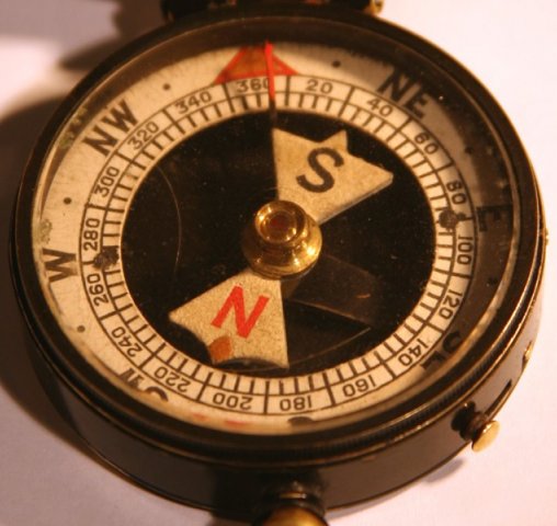
A First World War military compass
Using a magnetic compass seems at first sight to be relatively easy. Hold the compass level and allow the compass needle to settle down. The direction in which the needle is pointing will be north. If using a compass in conjunction with a map or chart, simply orient the map so that north on the map aligns with the direction in which the compass is pointing. There is however a problem, which is that magnetic north is not the same thing as true north. True north is the point in the northern hemisphere at which the Earth's axis of rotation passes through the Earth's surface - otherwise known as the North Pole. On most maps, directions are defined with respect to true north.
A compass needle actually points to magnetic north, which is the point in the northern hemisphere where the Earth's magnetic field points straight down. That point is currently located well over a thousand kilometers distant from the North Pole. To make things worse, magnetic north changes its position constantly, drifting by anything up to sixty kilometers per year. The difference between the direction in which a compass needle points and the direction of true north is called magnetic variation (or magnetic declination) The amount of variation encountered will depend on where on the Earth's surface the compass is being used. At the equator, the average variation is relatively small, but the further north you go (or south, in the case of the southern hemisphere), the greater it will be.
It is of course possible to compensate for magnetic variation for any location on the Earth's surface, providing the degree of variation at that location is known. To this end, the Earth's magnetic variation has been mapped numerous times since the seventeenth century, and maps and charts used for navigation often provide information about local magnetic variation. Some modern magnetic compasses can be manually adjusted to allow for such variation, enabling the user to obtain an accurate compass bearing.
Problems can also arise due to the presence of a local magnetic field, or the occurrence of electromagnetic interference. The degree of error introduced into compass readings due to such effects is called deviation. Local magnetic fields can be due to the presence of mineral deposits having magnetic properties (iron ore deposits, for example) or the use of large quantities of iron and steel in buildings, vehicles and ships. Electromagnetic interference can be generated by various sources, including electronic equipment, large electric motors, and vehicle ignition systems. In some cases, magnets are incorporated into the compass in an attempt to compensate for externally generated magnetic fields or electromagnetic interference.
The problems of magnetic variation and deviation were overcome thanks to the invention of the gyroscopic compass at the beginning of the twentieth century. As its name suggests, the gyroscopic compass relies on a high-speed gyroscope which, once it is spinning at full speed, is always aligned in the same direction. A gyroscopic compass will typically be set to point to true north (using a suitably calibrated magnetic compass or GPS data) and is then periodically checked (again using a compass or GPS data) to ensure that its accuracy is maintained.
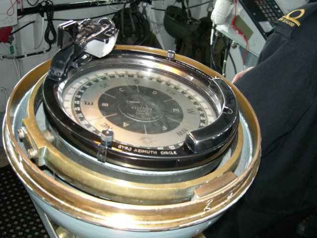
Gyro compass on the bridge of a Royal Canadian Navy destroyer - picture credit: Ken Walker
The advantages of the gyroscopic compass are that it always points towards true north, is not affected by local magnetic fields or sources of electromagnetic radiation, and does not depend on the shifting magnetic poles for its directional capabilities. It is also unaffected by the pitch and roll of a ship in heavy seas. The disadvantages are that a gyroscopic compass tends to be quite large and heavy, can be very expensive (tens of thousands of dollars), and requires a power supply. Most ships these days rely on GPS-based navigational systems (more about that shortly), with a magnetic compass providing a backup in the event of power failure or some problem occurring with the GPS service. Gyroscopic compasses are still used for military vessels, however - particularly submarines, for which a magnetic compass or GPS system is simply not an option.
The Astrolabe
An astrolabe is a kind of inclinometer or clinometer, also known as a tilt meter, gradient meter or slope gauge (among other things). As its various names suggest, it is used for measuring things like the angle of a slope, or the angle of elevation of an object above the horizon. Astrolabes have been used since ancient times, both for navigation and for pinpointing the position of various celestial objects. The astrolabe is believed to have been invented in Greece in around 150 BCE, possibly by the Greek astronomer and mathematician Hipparchus of Nicaea (circa 190 - circa 120 BCE). The example shown below dates from 1326 CE, and is known as the Chaucer astrolabe. It is one of the earliest known examples of a European astrolabe, and can be seen at the British Museum.
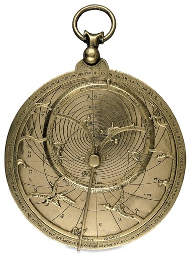
The Chaucer astrolabe © Trustees of the British Museum
An astrolabe like the one shown above is typically made of brass, and consists of a number of moving parts. The main body of the instrument is a large disk called the mater (which is Latin for mother) which has a raised border so that it can accommodate a number of thin, flat, circular plates. The ring around the edge of the mater (called the limb) typically has marks representing degrees or hours (or both). Each circular plate (or tympanum) is marked with circles representing altitude and azimuth for a particular latitude. The instrument can be dismantled and reassembled so that the tympanum most closely representing the latitude at which it is being used is on top of the others, and can thus be seen.
On top of this assembly sits a circular framework called the rete, through which the tympanum immediately beneath it can be seen. This framework includes a circular element called the ecliptic, which represents the path followed by the Sun during the course of a year, and various pointers that represent the positions of some of the brightest stars. Above the rete is an object that looks like a clock hand, called the rule. The whole assembly is held together by a central pin, allowing the rule and rete to rotate over the tympanum. The back of the instrument is engraved with scales that are used for measuring angles. A swivel-mounted ring at the top of the astrolabe allows it to be suspended using a chord during use.
The astrolabe is a versatile instrument that can be used for many different purposes, including timekeeping during both the day and night, determining the latitude of the user, and calculating the positions of stars, planets and other celestial objects. Astrolabe design became more sophisticated and increasingly ornate over time. Indeed, some examples could probably be considered to be works of art in their own right. The functionality of the astrolabe was also extended, to the point where it could be used for literally hundreds of different purposes.
Many fine examples of astrolabes were produced in the Islamic world during a period stretching from the ninth to the thirteenth centuries CE. During this time the Islamic empire included Spain, most of North Africa and the Middle East, and in the East it extended as far as the borders of China and India. Islamic explorers used the instrument to study the heavens for the purposes of navigation, whilst Islamic scholars made similar observations in order to determine prayer times, and to find the direction in which Mecca lay. Much of the scientific knowledge of the Islamic world eventually found its way to Europe via Spain, and a number of notable examples of astrolabes were produced in Europe during the Renaissance period.
The Quadrant
The quadrant is an instrument for measuring both the altitude of celestial objects and the angular distance between them. It is similar in in its basic functionality to the astrolabe, although somewhat less sophisticated and simpler in construction. It is believed to have first appeared around 150 CE following a design proposed by Claudius Ptolemy (circa 90 - circa 168 CE), an Egyptian-born Greek mathematician and astronomer (among other things). Ptolemy lived in Alexandria, and was a citizen of the Roman Empire. The quadrant is (as its name suggests) in the shape of a quarter-circle, and can be used to measure angles up to ninety degrees. In larger versions of the instrument, a moveable arm called a radius is attached to the apex of the quadrant, and is used to measure angles.
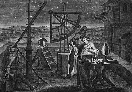
Artwork showing 17th century astronomers using a large quadrant
The illustration above is an early 18th century copperplate engraving on paper attributed to Philipp Florinus von Pfalz-Sulzbach (1630-1703), and shows astronomers at work. One of them is using a large quadrant, probably to measure the angles between various stars and planets. Like the astrolabe, the quadrant has been used for many different purposes, and many different types of quadrant have been created. Early versions of the so-called mural quadrant were created by drawing the outline of the quadrant on a suitable wall. Later versions were created by constructing a wooden or metal framework, which was then attached to a wall.
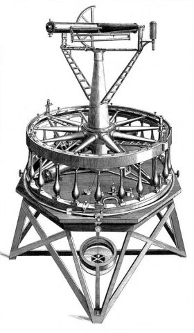
Other large quadrants were housed in their own frame. The frame-based quadrant shown below is one of the artifacts that can be seen in the pretelescopic Beijing Ancient Observatory in China, and was constructed in 1673. Mural and frame-based instruments were typically used to measure the altitude of, and angular distances between, celestial objects.
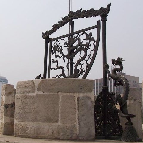
A frame quadrant at the ancient observatory, Beijing
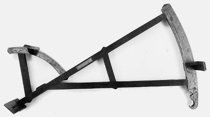
In gunnery, the quadrant was often used to measure the angle of elevation of the barrel of a cannon or other form of artillery. Quadrants of various types could also be used to determine the time. Other types of quadrant were used for surveying and navigation. The mariner's quadrant shown below (also known as a geometric quadrant) is part of a collection of nautical instruments housed at the National Maritime Museum, Greenwich, London, and dates from around 1725. It is made from brass, and the scale marked around the circumference (the limb) goes from zero to ninety degrees (0°-90°) in thirty second (30′) intervals. Note the sights at the top and bottom end of the right-hand edge of the quadrant, which form a simple alidade (an alidade is a device that allows an observer to determine the line of site between themselves and some distant object). As you can see, a plumb bob is suspended from a pin affixed to the apex of the quadrant.
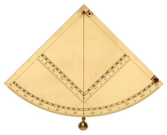
Brass mariner's quadrant © National Maritime Museum, Greenwich
In order to measure the altitude of some celestial object such as a star, the observer must hold the quadrant upright (i.e. in the vertical plane) and establish a line of sight to the object using the sights of the alidade. The idea is that you should be able to see the star (or whatever object you are interested in finding the altitude of) through both sights of the alidade. The plumb bob is allowed to hang down vertically, and the point at which it crosses the limb is read to give the angle of elevation. It could be quite difficult to maintain the instrument in the correct position and check the position of the plumb bob at the same time. Often, one person established a line of sight using the quadrant, while a second person recorded the position of the plumb bob. The accuracy of the instrument was limited by its size (smaller instruments tended to be less accurate than their larger counterparts). Accuracy was also rather dependent on the conditions in which the instrument was being used. High winds and heavy seas, for example, would have made accurate observations almost impossible.
The Cross-staff
The cross-staff is a navigational instrument, an early form of which is thought to have been invented in around 400 BCE in Chaldea (an ancient land bordering the upper end of the Persian Gulf), although its use for navigation does not appear to have occurred until the fourteenth century CE. The main component is a long wooden rod or staff, usually about thirty-six inches long, having a square cross-section and a graduated scale marked along its length on each of the four sides. The other components consist of much shorter vanes (cross-pieces) that are designed to slide back and forth along the length of the main staff. Each vane (of which there are usually four in number) is unique in terms of both its length and how it is graduated. When the cross-staff is in use, only one vane is used at a time, each being intended for use with the markings on a different side of the main staff.
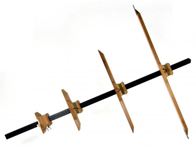
A reproduction of the 1720 Jochem Hasebroek Cross-staff
A full description of the reproduction 1720 Jochem Hasebroek cross-staff illustrated above, together with many other navigational instruments of historical interest, can be found at the website of Nicolàs de Hilster (http://www.dehilster.info). The website features a number of reproductions created by him, together with some very useful background information. The cross-staff gets its name from its cruciform appearance (it may also be occasionally referred to as a Jacob's staff or Jacob staff, although this name is also sometimes used to refer to other types of apparatus, so we will stick with the name cross-staff).
The cross-staff as we know it today was first described the Jewish mathematician Levi ben Gerson of Provence, France (1288-1344), although its invention is credited by some sources to Jewish astronomer and physician Jacob ben Makir ibn Tibbon (1236-1312) who also lived in Provence during the same period. The instrument has been variously used for astronomical observations, for surveying, and for navigation. It can be used to measure the angular height of an object relative to the user, or to measure the angular distance between two objects in the night sky.
The use of the cross-staff for navigation is believed to have first been suggested in 1514 by the German mathematician Johannes Werner (1468-1522). It was typically used to measure the elevation of the Sun at mid-day in order to find the current latitude of the observer. Each vane (or cross-piece) is used to measure a different range of angles. The user holds one end of the cross-staff close to one cheek in order to sight along its length, and slides the vane along the main staff until its lower edge lines up with the horizon and its upper edge lines up with the Sun. The vane is then held in place and lowered so that its position in relation to the markings on the main staff can be read. The reading gives the altitude (usually in degrees) of the Sun above the horizon.
A cross-staff in use (image credit: Canadian Museum of History)
In some ways, the cross-staff was ideal for use at sea as a navigational instrument. It was light, portable and relatively simple to make. On the other hand, it did suffer from some limitations. The instrument relied on the ability of the observer to accurately line up two different points simultaneously. However, the human eye is not actually capable of focusing on two different points at the same time, which meant that there was always the possibility of errors being made, particularly if the user was inexperienced. The margin of error is usually relatively small if the angle being measured is greater than or equal to twenty degrees (20°) and less than or equal to sixty degrees (60°). The further the angle falls outside this range, the greater the likelihood of error.
There was also the small matter of having to look directly into the Sun whilst measuring its altitude - never a particularly good idea, although the use of smoked glass provided a partial solution. The problem of having to look directly into the sun was eventually solved by the introduction of an instrument called the back-staff. This instrument measured the altitude of the Sun by allowing it to cast the shadow of a vane (called the shadow vane) onto another vane (the horizon vane) mounted at the front of the instrument. The user stood with their back to the Sun, and sighted the horizon through slits in the sighting vane (mounted at the rear of the instrument) and the horizon vane. The shadow vane would be moved along the forward arc until its shadow fell on the horizon vane, and its position on the arc then recorded. Easier to use than the cross-staff (although according to some sources less accurate), the back-staff gradually became more widely used. Eventually, both instruments would be superseded by the octant.
An 18th century back-staff (image credit: National Museum of American History)
The back-staff illustrated above is typical of those that had evolved by the mid-seventeenth century from the instrument originally designed by English navigator and explorer Captain John Davis (1550-1605) in 1594. The version designed by Davis, which became known as the Davis Quadrant, was a significant improvement on existing versions of the back-staff. It also overcame some of the shortcomings of other navigational instruments in use at the time, including the cross-staff, astrolabe and quadrant.
The Theodolite
The theodolite is an instrument used in surveying for measuring angles in both the horizontal and vertical planes. Its invention, in around 1571, is accredited to the English mathematician and surveyor Leonard Digges of Kent (1515-1559), although arguably its origins can be traced back considerably further. The Greeks used an instrument called a dioptra for measuring the position of stars in the night sky. This instrument was later adapted by the Romans for the purpose of measuring angles during surveying, and in this more evolved form had started to resemble its sixteenth century counterpart. Digges called his instrument a theodelitus, and it consisted of a divided circle and square with a compass in the centre, as illustrated below. Although equipped with a sighting device, it was missing the telescopic tube found in more modern versions. Digges' original design is believed to have been for an instrument capable of measuring horizontal angles only.
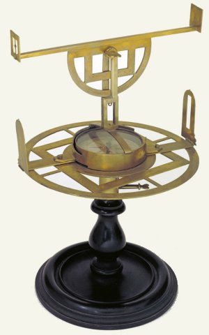
The theodelitus, invented in 1571 by Leonard Digges
The instrument originally designed by Digges consisted of a circular plate, marked around its circumference with graduations at one degree intervals, and having a compass at its centre. The whole assembly had to be carefully positioned so that the plate lay in the horizontal plane, and the compass was then used to orient the plate correctly. A rotating alidade (see above) enabled the user to establish the line of site between themselves and some distant target object. Its position relative to the graduated plate was then used to determine the angle of the target object relative to the user's position.
As you can see from the illustration above, a second alidade mounted on a semi-circular plate attached to the instrument in the vertical plane and capable of rotating around its vertical axis, was later added. This enabled an observer to measure vertical angles as well. By the middle of the eighteenth century, the alidades had been replaced by a single telescope, mounted on the vertical arc, which could be used to measure both horizontal and vertical angles. The use of a telescope also increased both the range and accuracy of the instrument.
The theodolite is generally considered to have become the modern, accurate instrument most contemporary surveyors are familiar with in 1787, when English mathematician and instrument maker Jesse Ramsden (1735-1800) built his famous Great Theodolite. The instrument was subsequently purchased by the Royal Society, and used to facilitate the calculation of the relative locations of the observatories at Greenwich and Paris by using a technique known as triangulation. Ramsden is notable for the fact that he created one of the first high-quality dividing engines. These devices enabled the graduations on navigational instruments to be marked with a degree of accuracy that had not previously been possible. In the years that followed, theodolites designed by Ramsden, which were capable of measuring angles to an accuracy of within a second of arc, were employed by the British Ordnance Survey to map most of southern Britain.
The Great Theodolite, built in 1787 by Jesse Ramsden
As we have already mentioned, the use of the theodolite in surveying relies on a technique known as triangulation. The technique is accredited to the Dutch mathematician, cartographer and instrument maker Gemma Frisius (1508-1555), and involves the establishment of a baseline between two points. The length of the baseline (which can be several miles in length) must be measured very precisely. A theodolite is then used to measure the angles between the baseline and the line of sight between each end of the baseline and the target point. Once these angles are known, and since the length of the baseline itself is already known, the position of the target point in relation to the baseline can be precisely calculated using basic trigonometry.
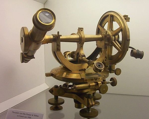
A theodolite built around 1900 by Otto Fennel & Sons - Zeiss Museum of Optics, Oberkochen
From the early part of the nineteenth century until the middle of the twentieth century, the techniques used to carry out geodetic surveys (i.e. surveys used to map large areas of land) remained relatively unchanged. From the 1950s onwards, significant advances in theodolite technology were made possible thanks to the availability of advanced electronic components, and the design of the instrument became increasingly sophisticated. Features such as automated targeting and distance measurement began to appear, culminating in the appearance of the modern "intelligent" theodolite. Theodolites are still used in many applications including, of course, construction, although the adoption of survey techniques involving satellite-based global positioning systems (GPS) in the early 1980s has largely obviated the need for the use of theodolites in geodetic surveys.
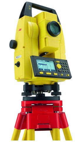
A modern theodolite - the Leica Builder 100 Series Digital Theodolite
As an aside, and for those interested in such things, we came across what the authors describe as:
"a multi-function augmented reality app that combines a compass, GPS, map, photo/movie camera, rangefinder, and two-axis inclinometer into one indispensable app. Theodolite overlays real time information about position, altitude, bearing, range, and inclination on the iPhone's live camera image, like an electronic viewfinder."
The app is one of several navigationally oriented apps marketed by Hunter Research and Technology, run by mechanical/aerospace engineer Dr. Craig Hunter, and is apparently available for iPhones and iPads on iTunes for just a few dollars – pretty amazing if it can do everything they say it can!
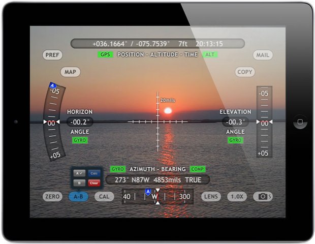
A screenshot of the Theodolite HD app marketed by Hunter Research and Technology
The Octant
The octant (sometimes known as the reflecting quadrant) is primarily a navigational instrument. As the name suggests, the octant has a shape that is one-eighth of a circle. The instrument relies on mirrors that reflect light along a path to the observer. The mirrors are arranged in such a way that they double the size of the angle that can be measured from one-eighth of a circle to one-quarter of a circle (i.e. a quadrant), or ninety degrees (90°). The octant is believed to have been invented by the English physicist and mathematician Isaac Newton (1643-1727) in around 1699, although a full description of Newton's instrument, which he passed on to the English astronomer and physicist Edmund Halley (1656-1742), was not published until after Halley's death (this was the same Edmund Halley, incidentally, after whom Halley's comet is named).
By default, therefore, the credit for the invention of the octant is generally attributed jointly to English mathematician John Hadley (1682-1744) and American inventor and optician Thomas Godfrey (1704-1749), who invented similar instruments independently in around 1730. Hadley generally gets the lion's share of the credit, probably because most of the significant developments relating to the development of scientific instruments during the eighteenth century were taking place in London under the auspices of the Royal Society. It is therefore Hadley's version of the octant on which we will focus our attention here. The drawing below shows Hadley's second version of the octant. This design will be far more recognisable to those interested in the history of navigation, since it is similar to that of the sextant (which we will discuss in due course).
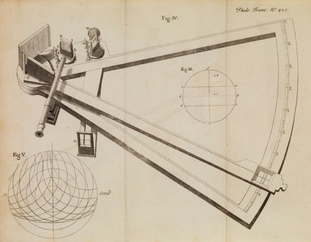
A drawing of John Hadley's octant © The Royal Society
From the drawing, you can probably see that the main frame of the instrument spans an angle of forty-five degrees (45°). A moveable arm (called the index arm) is mounted on the frame so that it can pivot around the apex of the frame. A narrow sighting telescope is mounted at the top of the instrument, near its apex (note that in use, the octant is held upright, with the telescope at the top). A mirror (known as the index mirror) is mounted on the index arm between the telescope and the apex of the frame, and moves with the arm. In the drawing you can see two smaller mirrors, one of which is directly in line of sight with the telescope, and the other to the right of it. These smaller mirrors are called horizon mirrors.
The horizon mirror in line of sight with the telescope reflects light from the index mirror through the telescope. The horizon mirror is small enough to allow the observer to see the horizon through the telescope (past the mirror) at the same time. Thus, the observer can see both the horizon and the object reflected in the index mirror (usually the sun or a known star) at the same time, without having to change the position of their eye. The index arm is rotated until the object being used for navigational purposes (which can lie anything up to ninety degrees from the line of sight) aligns with the horizon. The angle is then read off on a graduated scale, marked along the lower arc of the octant, through an aperture in the index arm. You can see a very nice demonstration of how the octant would have been used by navigators here.
The second horizon mirror, mounted perpendicular to the first, was intended for use with the telescope (which was detachable) mounted on the other side of the frame. The user could adjust the position of the telescope in order to see either horizon, as well as the object reflected in the index mirror. This allowed them to measure angles of up to ninety degrees from each horizon, giving a total coverage of up to one hundred and eighty degrees (180°), and enabling them to calculate the height of any object in the sky. Notice the shade mounted on the top of the octant. This was used to reduce the glare from reflected sunlight, but could be removed when measuring the height of objects in the night sky.
The octant became a popular instrument with navigators because of its relatively small size, light weight, and versatility. The ability to view both the horizon and the object whose height was being measured at the same time reduced the likelihood of errors. It was relatively easy to align the horizon and the reflected image, even if the ship experiencing significant movement due to pitch and roll, since from the observer's point of view they would appear to move together. An octant could be half the size of an equivalent cross-staff or back staff, with no accompanying loss of accuracy. It was constructed primarily of wood. Typically, the frame was made of mahogany or ebony, with the scale engraved on an ivory panel. Metal fittings were usually made of brass. On early versions, the mirrors were of polished metal. These were later replaced with silvered glass mirrors, once the technology for producing glass mirrors of sufficient quality had evolved.
The Sextant
The sextant is essentially a refinement of the octant in which the arc of the instrument is increased from one eighth of a circle (45°) up to one sixth of a circle (60°). Mirrors are used to double the angle that can be measured in exactly the same way they are in the octant, increasing the size of the largest angle that can be measured from ninety degrees (90°) to one hundred and twenty (120°) degrees. The development of the sextant as a replacement for the octant is largely due to the efforts of the Scottish Royal Navy officer and navigational expert John Campbell 1720-1790), whose experiences of using the Hadley octant led him to suggest increasing the arc of the instrument from forty-five to sixty degrees and replacing the wooden frame (which had a tendency to warp and split) with one of brass.
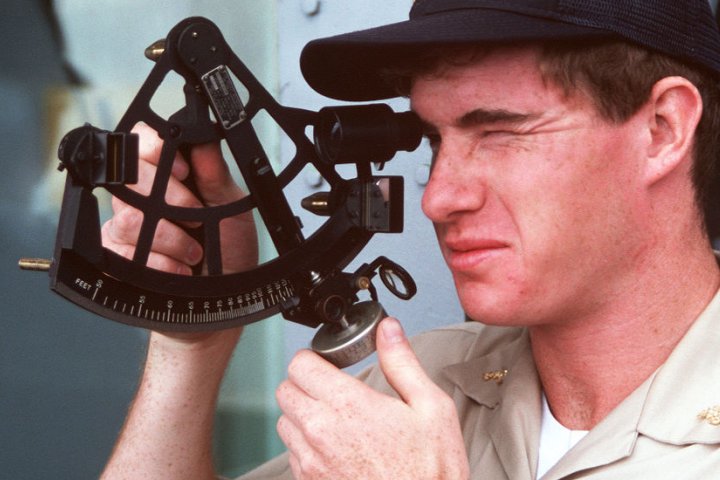
A US Navy midshipman taking a sextant reading as part of his training
Octants continued to be popular, mainly because they were easily manufactured, and because they were lighter and cheaper than the sextant, but the sextant became the instrument of choice for many navigators. The By the late eighteenth century, octants and sextants had essentially replaced all other navigational instruments. In fact, up until the end of the nineteenth century it was quite common to find both of these instruments in use on the same vessel. The octant would typically be used for routine daily measurement of the Sun's altitude, while the sextant (which was more accurate but heavier) was used for the measurement of the angular distances between objects in the night sky. In order to use these instruments to find one's geographical position, however, something else is required.
It had been possible for centuries for navigators to find their latitude (i.e. their distance north or south of the equator) by measuring the angular height of the Sun at mid-day. Navigators would measure their latitude when they left port on a voyage. For the return journey, they would sail north or south until they attained that latitude, then turn left or right as appropriate, and simply sail along the line of latitude until they reached their home port once more. What such measurements cannot reveal is the longitude of the observer, which is essentially a measure of how far east or west they are from a particular point (in modern navigational systems, longitude is a measure of how far east or west you are from the prime meridian, which is an imaginary line that runs from pole to pole via Greenwich, England).
In order to be able to calculate your exact position on the Earth's surface, you must have reliable maps and charts. You must also be able to measure both your latitude and your longitude. By the eighteenth century, thanks to centuries of meticulous astronomical observation and record keeping and the availability of mathematical techniques such as spherical trigonometry, astronomers were able to accurately calculate the relative positions in the night sky of the Sun, Moon, stars, and planets at different times throughout the year. This information was carefully recorded and compiled into tables which, together with the fact of the Moon's relatively rapid transit across the night sky, provided navigators with a means of finding their longitude from anywhere in the world.
Because the moon is in orbit around the Earth, and because it is much closer to the Earth than any other celestial body, it travels across the night sky relatively quickly by comparison with the stars and planets. Using the observational data collected, astronomers were able to perform the calculations required to predict where the Moon would be in relation to a particular star or planet, i.e. the angular distance between them, at any time of the night or day. In fact, they could predict these "lunar distances", as they called them, for several years in advance. At any given moment, the angle measured between the Moon and a particular star or planet (or, indeed, the Sun) would be the same, regardless of the observer's location on the Earth's surface. Complete tables of these lunar distances were compiled into publications called nautical almanacs.
Most importantly, the time at which a particular lunar distance would occur was calculated using Greenwich time (i.e. the local time at the Greenwich observatory in London, England). This meant that an observer could measure a lunar distance (using a sextant) and consult their almanac in order to determine the current time at the Greenwich observatory. In order to calculate their longitude, the observer need only determine the difference between the time in Greenwich and the local time. A difference of one hour represented an angular distance of fifteen degrees from the Greenwich meridian. Of course, there was also the small matter of correctly determining the local time. This could be established fairly easily, however, by measuring the height of the Sun or a suitable star.
Although the above description probably makes the task of establishing longitude sound relatively easy, in reality things were a lot more complicated. The Moon is a relatively large object in the night sky, and may appear larger or smaller depending on latitude and the precise distance of the Moon from the Earth at any given time. Furthermore, because the Moon is relatively close to the Earth (by comparison with the stars and planets), its position as measured by an observer can vary by anything up to a whole degree of arc, depending on precisely where the observer is. There were of course mathematical methods available to navigators to allow them to compensate for such factors and eliminate errors, but they were time consuming and tedious. Navigation became easier once reliable and accurate marine chronometers, synchronized to the time in Greenwich, became available.
The available of GPS technology for commercial use has meant that a sextant is no longer needed for navigation. The use of a sextant is nevertheless still part of the training undertaken by navigators, and still features in navigational exams. The reason for this is simple; navigational aids based on GPS technology are dependent on both the availability of electrical power and the continued presence of a functional GPS satellite network. Given the possibility that either or both of these resources could be compromised, however unlikely that may seem the availability of a sextant, and the knowledge required to use it, ensures that navigators will still be able to find their location.
The Global Positioning System (GPS)
The Global Positioning System (GPS) is a satellite navigational system developed by the United States Department of Defense during the 1970s for military use. Since 1980, GPS technology has been available for commercial use, and is now used in countless applications including navigation, surveying, cartography and vehicle tracking systems. The first GPS satellite was launched in 1978, with at least one satellite per year being launched since that time. In order to provide full global coverage, the GPS system requires a "constellation" of at least twenty-four satellites. Full operational status was achieved by the mid-1990s, when the number of GPS satellites in orbit reached the required number. Because each satellite can remain fully functional for only a few years, new satellites must be launched on a regular basis to replace those that have reached the end of their useful life.
At the time of writing, the GPS constellation consists of thirty-one satellites, providing considerable redundancy in the system. Each GPS satellite is maintained in a medium earth orbit at a height of just over twenty-thousand kilometers, in one of six orbital planes. The orbital period is approximately twelve hours, which means that each satellite orbits the Earth twice each day. The orbits are designed to ensure that a minimum of six satellites are in line of sight for virtually any position on the Earth's surface at any time of the day or night. The position of each satellite is monitored by monitoring stations around the globe. This information is sent to a master control station in the United States. The master control station uses a number of ground antennae to regularly update each satellite with its current position and a clock signal to enable the satellites to synchronise their internal clocks.
Each satellite carries a highly stable atomic clock, enabling the clocks of the entire GPS constellation to remain synchronised to the clock signal transmitted by the master control station to within a few nanoseconds. Each satellite continually transmits status information, including its current position and the time according to its onboard clock. A GPS receiver is tuned to receive signals at the frequencies used by the GPS satellites. A typical GPS receiver can receive signals on up to twenty different channels, although it need only have line of sight to four different channels in order to establish its geographical location and the time difference between its internal clock and the clock on board the satellite.
The GPS receiver can calculate the time taken for a signal from a particular satellite to reach it by comparing the time of transmission encoded in the satellite's signal with the time of arrival of the signal according to the receiver's clock. Since the speed at which the signal propagates is known (i.e. the speed of light) the distance between the satellite and the receiver can be accurately calculated. Together with the satellite position data encoded in each satellite's signal, this information allows the receiver to calculate its longitude, latitude and altitude (usually expressed as height above sea level) to an accuracy of between three and fifteen metres, as well as the current time.
The process by which the GPS receiver calculates its position is called trilateration. This is defined as determining the absolute or relative position of a point in space through the measurement of distances, using the geometry of circles, spheres or triangles. If you know you are at a distance x from satellite A, you can think of yourself as being on the surface of an imaginary sphere of radius x, with its centre at A's coordinates. If you also know you are at distance y from satellite B, you will also be on the surface of another imaginary sphere of radius y, with its centre at B's coordinates. The two spheres will overlap, and intersect in a circle. Your location will lie somewhere on the circumference of that circle.
Now let's suppose there is a third satellite - satellite C - at distance z. Once again, you will be somewhere on the surface of an imaginary sphere of radius z, with its centre at C's coordinates. The overlap between all three spheres, however, now occurs at just two points, one of which will be your location. If you think of the Earth itself as the fourth sphere, only one of the two possible points will lie on its surface. For this reason, three satellites are generally sufficient to establish the latitude and longitude of a GPS receiver. A fourth satellite, however, can be used to provide both greater accuracy and altitude information. Provided the receiver knows the location of each satellite, and the distance between it and each of the other satellites, it can make the necessary calculations.
How trilateration works to determine GPS position