Entity Life Histories
The purpose of an information system is to provide up-to-date and accurate information. The information held on the system is constantly changing - the number and names of the patients on a hospital ward, for example, or the price of electronic components. The system must be able to keep track of such changes. An entity life history (ELH) is a diagrammatic method of recording how information may change over time, and models the complete catalogue of events that can affect a data entity from its creation to its deletion, the context in which each event might occur, and the order in which events may occur. The ELH represents every possible sequence of events that can occur during the life of the entity. Remember that, although data is changed by a system process, the occurrence of that process is triggered by some event.
It would obviously be an overwhelming task to model the all of the events that could affect the system data at the same time, so instead we examine just one entity within the logical data structure at a time. An entity life history will be produced for each entity in the logical data structure. Information from the individual life histories can be collated at a later time to produce an entity/event matrix.
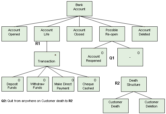
The diagram below shows how we might model the life history of a bank account entity.
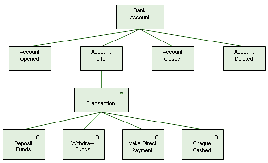
An entity life history for the "Bank Account" entity
The entity life history for "Bank Account" should accommodate any possible occurrence of that entity. All bank accounts must be opened, and money is either paid in or withdrawn. The diagram itself is read from left to right. If the structure branches downward, the branch must be followed down before moving on towards the right-hand side of the diagram. The first event to affect any occurrence of "Bank Account" will be the opening of the account. The account will have a life, which will consist of a series of transactions. Transactions can include the deposit or withdrawal of funds, direct payments, or the cashing of cheques. After an unspecified number of transactions have occurred, the account will be closed, and eventually deleted. The entity life history elements featured in the above example are:
- Sequence - activities are undertaken in strict sequence, from left to right (for example, an account must be opened before any other event that will affect it can occur, and account closure must occur before account deletion).
- Iteration - the asterisk in the top right-hand corner of the Transaction box signifies that a transaction is an event that can occur repeatedly.
- Selection - boxes with small circles in their top right-hand corner represent alternative forms of transaction. A single transaction may be a deposit or a withdrawal of funds, a direct payment, of the cashing of a cheque.
" In the same way that an entity may be affected by several different events, a single event may affect more than one entity. When an instance of "Bank Account" is created, for example, an instance of "Customer" must also be created. The interaction between an event and an entity is called an effect. Notice that elements that have an effect on an entity have no other elements below them in the entity life history diagram. Elements that do have other elements below them are called nodes. They have no significance other specifying the sequence in which events may occur within the context of the entity's life history. The name of each element (shown as a label inside the box representing the entity) reflects the event affecting the entity (if the element is an effect) or a particular stage within the life history (if the element is a node).
Although an entity life history can be constructed using only the elements sequence, iteration and selection, the representation of certain complex scenarios can be greatly simplified using two additional element types:
- parallel structures
- quit and resume
Sequence
A sequence consists of a series of nodes and/or effects reading from left to right, as shown below.
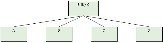
Boxes A, B, C, and D represent a sequence
In the above example, effect A will always occur first, followed by B, then C, then D. This is the only possible sequence. Although these sequential events will take place over a period of time, the time intervals involved are unspecified, and could range from a few seconds to many years.
Selection
A selection defines a number of nodes or effects that are alternatives to one another at a particular point in the entity's life history. A circle in the top right hand corner of the box representing the element indicates that it is one of several elements that could be chosen.
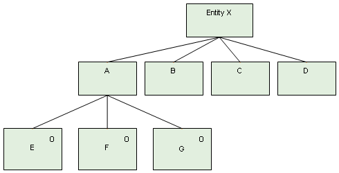
Boxes E, F and G represent the available options
Because node A is the first element in the entity life history of "Entity X", an occurrence of the entity can only be created by event E, F or G. If we want to represent the fact that none of the available options have to be selected, we can include a null box, as shown below.
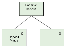
A null box indicates that an option does not need to be selected
Iteration
If an event or node can occur repeatedly at the same point within an entity's life history, the fact is signified by an asterisk in the top left-hand corner of the box representing the event or node. The only restriction on iterations is that a single occurrence of the iteration must be complete before the next one starts.
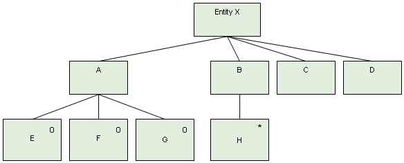
Event H may occur repeatedly
Once "Entity X" has been created by event E, F or G under node A, event H can affect the entity zero or more times The iteration symbol must not be used for events or nodes that occur only once, or not at all (use the null box instead).
Parallel structures
A parallel structure can be used if the sequence in which two nodes or events can occur is unpredictable, or where they may occur concurrently. Such a structure is shown as two nodes or events connected by parallel horizontal lines, as illustrated below.
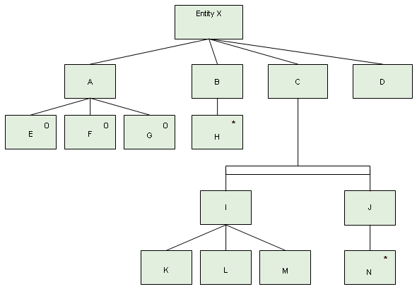
Nodes I and J form a parallel structure
In the entity life history above, the events K, L and M may occur, in that order, under node I. At the same time event N, under node J, may occur zero or more times. Nodes I and J (representing the sequence and the iteration respectively) are connected by a parallel bar to signify possible concurrency. The same situation could be modelled using only sequence, iteration and selection elements, but the resulting diagram would be far more complex and consequently more difficult to interpret.
Quit and resume
Occasionally, a situation can arise that cannot easily be modelled using the entity life history elements already described. In order to accommodate such situations without making the entity life history diagram unduly large or complex, the quit and resume facility allows the sequential progress of nodes or events to quit at one point in the entity life history and resume at another point. This concept is illustrated below.
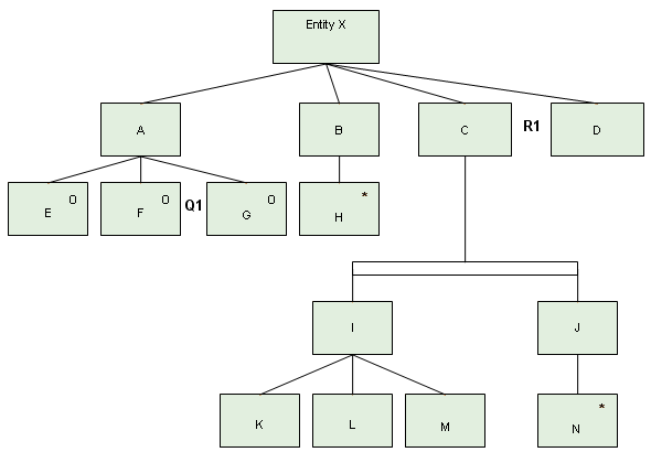
Following event F, activity will continue at node C
In the above example, event F has the label "Q1" immediately to its right, and node C has the label "R1" immediately to its right. Using this notation, we can signify that the event or node that will follow event F is whichever element has the label R1 to its right, which in this case is node C. As with parallel structures, the same situation could be modelled using only sequence, iteration and selection elements, but the resulting diagram would be more complex and difficult to interpret.
The example below shows how we can model a situation in which a bank account has been closed (but not deleted), and is then re-opened. The event Account Reopened (labelled Q1) causes a quit back to the node Account Life (labelled R1).
Two possible uses of quit and resume
The quit and resume facility also allows us to quit from the main structure altogether, and resume at a point in a stand-alone structure. This can be used in situations where an event that can occur at any time will alter the normal sequence of the life history. Since it is impossible to predict exactly where such an event might occur within the entity's life history, an appropriate instruction should be added to the diagram indicating the circumstances under which the quit might occur, and from where. In the above example, the death of a customer may occur at any time after an account is opened, triggering an immediate quit, followed by a resume at R2 (Death Structure). In circumstances such as the death of a customer, the normal sequence will no longer apply.
Note that it is also possible to quit from a stand-alone structure back to the main structure in an entity life history. To avoid ambiguity, while there may be more than one quit point with the same identifier, there cannot be more than one resume point with that identifier.