Logical Data Modelling
In order to design an information system, it is necessary to know what information is to be held and how it should be organised. To this end, we can create a logical data structure (LDS) that allows us to see how related data items are grouped together, and how the various groups (or entities) relate to each other. Entities represent things about which we store information, such as customers, suppliers, orders, or employees. In our model, the entity "Customer" will be used to represent all customers about whom we hold information. An entity is shown on a logical data structure diagram as a rectangular box, with the name of the entity inside it.
The data items that make up an entity are referred to as attributes. An attribute is a discrete item of information about an entity, such as age, surname, or product code. Each attribute will have its own data type, depending on what kind of information it represents. Because we need to be able to uniquely identify every instance of an entity, one of the attributes of an entity (or possibly a combination of two or more attributes) must be unique for that entity within our system. For an occurrence of the entity "Customer", for example, we might have a unique alphanumeric code. An attribute (or combination of attributes) that is used in this way is known as a primary key.
Entities have relationships with other entities. In a hospital information system, for example, we might hold information about wards, and the patients in those wards. Both patients and wards can be represented in our logical data structure by entities, and there is clearly a relationship between the two. For any given patient, our information system should be able to tell us in which ward that patient is being accommodated. Conversely, for any given ward, the system should be able to provide us with a list of patients. The relationship between patients and wards is illustrated below.
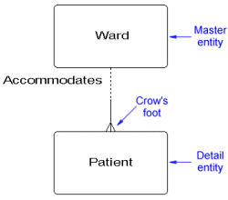
A one-to-many relationship
The relationship shown in the above LDS is a one-to-many relationship in that one occurrence of ""Ward" may have many occurrences of "Patient" associated with it. The crow's foot is used to signify the 'many' end of the relationship. The entity at the 'one' end is usually referred to as the master entity, while the entity at the 'many' end is referred to as the detail entity. One-to-many relationships are by far the most common type of relationship to be found in a logical data structure. There are three possible degrees of relationship:
- one to many
- many to many
- one to one
Most relational database management systems are not designed to handle many-to-many relationships. For that reason they are to be avoided when creating a logical data structure. Consider the logical data structure shown below, which represents the relationship between patients and drugs in a hospital.

A many-to-many relationship
A patient may be prescribed any number of different drugs, and a drug may be prescribed to any number of different patients, so we would seem to have a many-to-many relationship. If we consider the prescription itself to be an entity, however, we can create a somewhat different model. A prescription will have attributes such as the prescription date, the name of the drug prescribed, and the frequency and dosage to be taken. By definition, a prescription can only be for one patient, although a patient may have any number of prescriptions. We will also stipulate that the definition of a prescription means that it can only be for one drug, although obviously the same drug may appear on many prescriptions. We can now produce a revised LDS, as shown below.
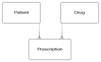
Patient and Drug are linked via Prescription
The many-to-many relationship has been replaced by two separate one-to-many relationships. A patient may have many prescriptions, but a prescription can only be for one patient. Similarly, a drug can be prescribed by many prescriptions, but a prescription can only be for one drug. The entity "Prescription" is thus a detail entity for two relationships. We call an entity that links together other entities in this way a link entity. Wherever many-to-many relationships exist, we should be looking to create a link entity and two one-to-many relationships.
One-to-one relationships are also often undesirable in a logical data structure, although there are obviously examples of groups of information that are related to one another in this way. Take the example of "Employee" and "Curriculum Vitae".

A one-to-one relationship
Obviously, since an organisation should hold only one curriculum vitae for each employee, and a curriculum vitae will certainly only concern one employee, there is a one-to-one relationship between the two. In most cases, however, the two entities can be merged to create a single entity.
We should also consider the question of whether a relationship must always exist between two entities, or whether the existence of a relationship is either optional or dependent on other factors. We may, for example, have an entity called "Customer" to represent organisations or individuals to whom we are intending to sell something. We will have another entity called "Order" to represent the sales orders which we hope will be generated. There will obviously be a one-to-many relationship between "Customer" and "Order", since an order can only relate to one customer, but a customer may place any number of orders. At some point, however, we may have customers on our books that have not yet placed an order, perhaps because they are still evaluating a quotation. So, while an occurrence of "Order" cannot exist without a related occurrence of "Customer", the reverse is not true.
In any one-to-many relationship between a master entity (A) and a detail entity (B), there are four possible states in which the relationship between these two entities could exist:
- Mandatory at both ends - if an occurrence of A exists it must be associated with at least one occurrence of B. If an occurrence of B exists, it must be associated with one (and only one) occurrence of A.
- Optional at the master end and mandatory at the detail end - if an occurrence of A exists it may be associated with at least one occurrence of B. If an occurrence of B exists, it must be associated with one (and only one) occurrence of A.
- Mandatory at the master end and optional at the detail end - if an occurrence of A exists it must be associated with at least one occurrence of B. If an occurrence of B exists, it may be associated with one (and only one) occurrence of A.
- Optional at both ends - if an occurrence of A exists it may be associated with at least one occurrence of B. If an occurrence of B exists it may be associated with one (and only one) occurrence of A.
In practice, optional relationships are generally considered to be those in which it an occurrence of the detail entity can exist without its corresponding master. In a one-to-many relationship, the connecting line between the master and detail entities is usually shown as a solid line if the relationship is mandatory, and a broken line if the relationship is optional.
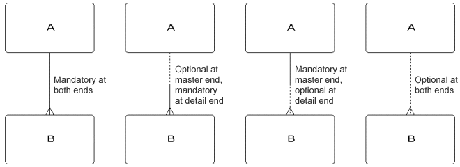
There are four possible states for one-to-many relationships
Sometimes, it is possible for an entity to have a relationship with one entity that precludes a relationship with another entity, or vice versa. Consider the LDS below. The detail entity B can be in a relationship with master entity A or with master entity C, but not with both. The arc on each of the connecting lines (identified in this case by the letter a) indicates that these relationships are mutually exclusive.
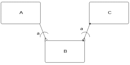
Mutually exclusive relationships
In some cases, multiple relationships can exist between the same pair of entities, where the only other way of avoiding a many-to-many relationship would be to create an artificial link entity. Think about trying to model the relationship between teams in a local football league and fixtures. Every team in the league will have many fixtures, and each fixture will involve two teams. We thus appear to have a many-to-many relationship between "Team" and "Fixture".
Rather than create an artificial link entity to eliminate the many-to-many relationship, we can use the fact that only two teams can be involved in any one fixture and create two one-to-many relationships as shown below. When two or more relationships exist between entities in this way, it is a good idea to label them to avoid confusion.
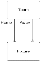
Entities can be linked by multiple relationships
Logical data structure diagrams should be easy to understand. They should, as far as possible, be drawn so that the lines representing relationships do not cross. Entities that relate to the same area of business activity should be grouped together (this will often occur naturally, since they will tend to have relationships with one another). One of the conventions used when drawing the LDS is to try to place the crow's feet so that they appear on the top of the detail entity in a one-to-many relationship. This makes the diagram easier to follow, since master entities will always be above their detail entities.
The LDS should be validated against the data flow diagrams to ensure that all of the processing shown in the DFDs is fully supported. The data items required for the processing must be included in entities, and the relationships between entities must be in place to enable the all of the required data retrieval operations.
The documentation required to support the LDS will include an entity description for each entity in the LDS. The description should include the names of any master and detail entities with which the entity being described has a relationship, volumetric information about the entity (the average and maximum number of occurrences for the entity), a list of the entity's attributes, and the identity of the attribute (or attributes) used as the entity's primary key.
