Class Diagrams
A class diagram describes the structure of a system (or part of a system) in terms of the classes that exist within the system and the relationships that exist between them. A class is essentially a template from which any number of objects can be derived. It does not exist as an object in its own right, but it defines the properties (or attributes) that an object will have, and the operations that can be performed by the object. The class BankAccount, for example, will define attributes such as accountNo and balance. The operations defined for the BankAccount class could include functions such as returnBalance() or updateBalance(). An object of type BankAccount is an instance of the BankAccount class. Here is an example of the icon used to represent such a class within a class diagram:
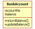
The BankAccount class
The icon is essentially a rectangle, divided into three sections by horizontal lines. The top section contains the name of the class (BankAccount). The middle section contains the class attributes accountNo and balance. Note the minus sign ("-") in front of the name. This indicates that these attributes are private, i.e. they can only be accessed by the operations defined for the class and cannot be "seen" by other parts of the system. The bottom section contains the operations that can be carried out by the class, returnBalance() and updateBalance(). The operations have a plus sign ("+") in front of them showing that they are public, which means that access to them is unrestricted. The notion of classifying UML class attributes and operations as either private or public reflects the way in which class variables and methods in object oriented programming languages are declared. The idea (usually) is to hide the data items that belong to a class, while allowing access to them via the methods defined for that class.
You might like to make a note of the naming conventions used here. If a class, attribute or operation has a name that contains more than one word, there is no space between the words. The name of the class has a capital letter at the start of each word it contains. For attribute and operation names however, the first word should always start with a lower-case letter. The name of an operation is followed by a pair of parentheses. Still on the subject of naming things, the attribute names used should reflect, as far as possible, the nouns used to describe the things they relate to in the real world environment being modelled. The same holds true for the names used for operations, which should reflect the verbs used to describe operations that occur in the real world domain. These nouns and verbs will have emerged naturally during consultations with the client, and incorporating them into the system namespace will aid the client’s understanding of the UML model.
A class diagram usually includes a number of class icons, connected together by lines that indicate the type of relationship that exists between the interconnected classes. They provide a static view of the system, because although they show the relationships between the various classes they provide no information about what actually happens when these classes interact. Because they map so closely to the real world entities that comprise the system, class diagrams are a useful tool for enabling analysts to explain the system to clients. By the same token, they are also useful for enabling clients to discuss the problem domain with analysts. Once completed, they will form a design blueprint that can be used by programmers to create the application’s data structures and program logic. Here is a class diagram that might be used to represent a simple bank system:
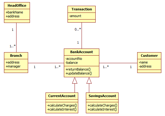
A simple bank system class diagram
The class diagram shown above was created with StarUML, which is a freely available open source UML modeling tool. Note that the class diagram for a system will inevitably be modified as more information is discovered about the classes, their attributes and operations, and the relationships that exist between them. The class diagram we will use in the design stage of a project will probably differ significantly from the class diagram we start out with in the early stages of the analysis process. It will certainly be more detailed, as we refine our knowledge of the system requirements. The class diagram above tells us quite a lot about the system, but some important details are missing. Let's examine each feature of the diagram and see how it might develop as we progress.
Attributes
The attributes of a class (assuming there are any) are listed in the middle rectangle of the class icon, and represent some item of data that can be recorded about an instance of the class. An instance of the class BankAccount will have a unique account number, and an account balance that will vary over time. These attributes will be represented as data items in our application software, and in the system database. We should at some point therefore specify the data type that is to be used for these attributes. This is a good example of how software designers can communicate their requirements very precisely to programmers. UML allows you to specify the data type for an attribute (e.g. string, integer, floating-point, Boolean etc.), and an initial default value. Below is a modified version of the BankAccount class that demonstrates the principle.
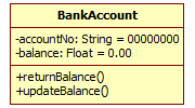
The BankAccount class showing attribute types and initial values
The accountNo attribute is now shown as having the type String, while the balance attribute has the type Float. Both of these types are generic UML data types (other UML data types include the types Integer and Boolean). The accountNo attribute has been assigned the initial string value "00000000", while the balance attribute has been assigned an initial floating point value of zero (0.00). Note that most UML modeling tools will allow you to specify a data type that is specific to a particular object oriented programming language such as C++ or Java. This is useful if you already have a target programming language in mind when designing your application.
Operations
An operation is a task that the class can carry out in response to some trigger (usually a request from another part of the system). The operations defined for a class are listed in the bottom rectangle of the class icon, and the name of the operation is always followed by parentheses (brackets). The parentheses in the examples you have seen so far have been left empty, but they often contain the names and data types of one or more variables that will be passed to the operation as parameters (usually referred to by programmers as arguments) by whatever system entity has requested that the operation be carried out. The execution of an operation will usually generate some result that will be passed back to the requesting entity. The name and data type of this return value, if included, appears after the parentheses and is preceded by a colon. The parameter(s) that an operation takes, together with any return value, constitute the operation's signature. Here is the BankAccount class once more, amended to show the signatures for the two operations so far defined for it:
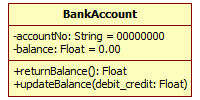
The BankAccount class complete with operation signatures
The purpose of the returnBalance() operation of the BankAccount class is simply to return whatever the current balance of the account happens to be. The operation therefore does not need any parameters, but will return a floating point value that represents the balance of the account. The updateBalance() operation, on the other hand, does not need to return a value. It does, however, require an amount by which to increment or decrement the account balance, and this is passed to the operation as a parameter named debit_credit of type Float.
It is worth noting at this point that once you start to add attributes and operations to a class, together with the associated parameter and data type information, the class icon will quickly grow. The effect of adding all of this additional information to a class icon can often be to make class diagrams look somewhat cluttered (bearing in mind, of course, that a class diagram may contain a significant number of class icons). It is perfectly permissible to hide any information that is not of immediate consequence in the interests of preserving clarity. To this end, many UML software tools allow you to hide the contents of the attribute and operation sections of the class icon in a class diagram.
Responsibilities and constraints
The responsibilities of a class are generally considered to be its attributes and operations (i.e. the data it contains and the actions that it will be perform). Sometimes, in order to eliminate possible ambiguities, these responsibilities may be described in writing in an informal way. Depending on the UML software tool being used, it may or may not be possible to include this information within the class icon. This would typically involve an additional section being added to the class icon below the operations section (of course, if you were drawing the diagrams by hand, no such restrictions would apply). In some UML software tools, it is possible to create a note containing further information about a class that can be attached to the class icon, or connected to it via a dotted line.
The removal of ambiguity can be achieved in a slightly more formal way by using constraints. Constraints are rules that are applied to class elements. In the BankAccount class, for example, the accountNo attribute should always be an eight-digit numeric string. The constraint may be expressed either in natural language (which is easy to understand) or using the Object Constraint Language (OCL), a text-based language used to define rules for UML models and model elements. The constraint consists of a text string that defines the rule (either formally using OCL or informally using free text), enclosed within a pair of curly braces ("{ . . . }"). The rule for our accountNo attribute, for example, would specify that the string value assigned to this attribute for any instance of the BankAccount class must consist of exactly eight characters, and that each character must be a numeric character, i.e. 0, 1, 2, 3, 4, 5, 6, 7, 8 or 9.
Associations
A class diagram, as the name suggests, shows all of the classes in a system. Class icons alone, however, only tell part of the story. We can draw lines to connect the various classes together in order to show the relationships that exist between the various classes. These connections, when they appear on class diagrams, are usually referred to as associations. The connecting line may have an arrowhead at one end to indicate which way the association works, and a label that provides a name or brief description of the relationship. If no arrowhead is present, the association is assumed to be bi-directional. Depending on the UML software tool you are using, you may also have the option to place labels at either end of the line that represents the association to describe the role of each class.
Let's consider the relationship between employers and employees. We can represent employers using a class called Employer, and employees using a class called Employee. We can also use an association to model the relationship between these two classes as shown below. We have labelled the association "Is employed by", and the association has an arrowhead pointing at the Employer end (to indicate that the employee is employed by the employer).

Associations between classes are shown by lines
We have already seen that each class on a class diagram can be connected to a number of other classes, but so far we have only seen a single association between any two classes. The relationship between classes can be seen differently, however, depending on the role each class plays. The relationship between an employer and an employee is a good example of this, because the employee works for the employer, whereas the employer employs the employee. We can show how the relationship differs, depending on the direction in which we look at it, as shown below.

More than one association may exist between two classes
Although the employer-employee relationship is a fairly trivial example of an association that can be seen from different perspectives (and one that shouldn't really need to be highlighted), it is perfectly acceptable to show two (or more) associations between classes. This is often done in order to draw attention to the fact that the interactions between the two classes may differ, depending on the direction in which they act.
An association between two classes may also be subject to some kind of rule. For example, supposing we are trying to model a timetabling system for a bus company. We might create a class called BusRoute to represent the bus routes operated by the company, and another class called BusStop to represent the locations covered by those routes. A bus route will consist of a list of stops that it must call at, including the stop at which the route starts and the stop at which it terminates. For a given route, the order in which the bus calls at each stop does not vary; it will call at each stop on the list in a specific order. We can show this constraint on the association between BusRoute and BusStop by using the word ordered enclosed within curly braces, as shown below. The constraint is placed near the association line, and close to the BusStop class.

Constraints are shown in curly braces
The association between two classes may well have attributes and operations in its own right, which means that it could be represented by a class icon in the same way that other entities in our model are represented. In the UML, there is a special kind of class called an association class that is used to model such an association. The association class has its own icon, which is connected to the association to which it belongs via a dashed line. In the class diagram below, the association between an employer and an employee is represented by an association class called Contract, which has attributes that represent the details of the contract of employment issued by the employer to the employee. An association class can have an association with another class, as shown here. The association class Contract has an association with the HRManager class.
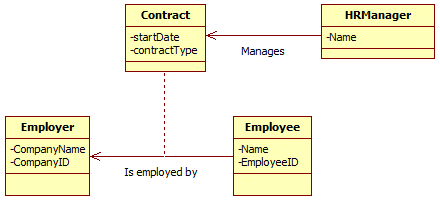
An association class can be linked with other classes
The multiplicity of an association may also be shown on a class diagram. The multiplicity of a relationship essentially tells us whether the relationship between two classes is a one-to-one, one-to-many, or many-to-many relationship. In the case of a one-to-many relationship, the notation used must tell us which end of the association represents the one and which end represents the many. Multiplicity is represented in class diagrams by including the appropriate notation at each end of the association. The table below shows the different types of multiplicities that may be found on an association, and how they are represented.
| Notation | Number of instances |
|---|---|
| 0..1 | zero or one instance |
| 0..* or * | zero or many instances |
| 1 | one instance |
| 1..* | one or many instances |
In the UML notation used here, the asterisk represents the word more (or many) and the two dots represent the word or. Probably the most commonly occurring type of relationship in a well-designed business information system is the one-to-many relationship. For example, an order may have many order items on it, but an order item can only belong to one order. A customer may place many orders, but an order may only relate to one customer. Below is part of the simple bank system class diagram we saw earlier.
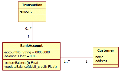
Part of the simple bank system class diagram
The association between the BankAccount and Transaction classes has a one-to-zero-or-more relationship. From the point of view of our system, a transaction can only relate to one account (the account must exist in order for there to be the possibility of a transaction being made). When the bank account is first opened, there will be zero transactions, so at that point in time we have a one-to-zero situation (one bank account, zero transactions). Over time, however, we can expect a number of transactions to be made. Even if the account is closed again immediately after it is opened (unlikely as that might seem), the multiplicity holds true because it allows for zero transactions.
The association between the Customer and BankAccount classes is characterised by a one-to-one-or-more relationship. A bank account can only belong to one customer (we make the assumption here that, for a joint account opened by close relatives or business partners, the parties jointly owning the account will be treated as a single customer entity). A customer, on the other hand, might have several accounts (e.g. current account, savings account, business account, and so on). At the BankAccount end of the association, the multiplicity is going to be one-or-more rather than zero-or-more. This is because, due to the nature of a bank, a customer is not a customer until they have opened some kind of account.
One of the less common types of association is the association a class may have with itself. This type of association is called a reflexive association, and only occurs when a class may have more than one role. The diagram below shows how an Employee class could be related to itself if an instance of this class has a manager role. Bear in mind that the instance of Employee being managed will be a different instance to that which manages it.
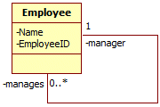
A reflexive association
Generalisation and inheritance
Programmers that use an object-oriented language such as C++ or Java will be familiar with the idea of inheritance in the context of classes. In the UML, the word generalisation is used instead of inheritance, but it means more or less the same thing, which is that one class can be a sub-class, or child class, of another class (the parent class). The child class will have a different name, but inherits all of the characteristics of the parent class including its attributes and operations. Child classes tend to be specialisations of their parents and may have additional attributes and operations that the parent class does not have.
Nature provides some good analogies to help us understand generalisation. If we think of Animal as a parent class, we can think of Mammal as a child class. Mammals have all of the characteristics attributable to animals because they are . . . well . . . animals! They have a number of specialised features, however, that define them as mammals. So while all mammals are animals, not all animals are mammals. The class Mammal is therefore a specialisation of the class Animal (which is a generalisation). Both classes have some attributes in common (e.g. species, heterotrophic type etc. (a heterotroph is a living organism that must ingest other organisms or their by-products to sustain life). The Mammal class, however, has an additional set of characteristics that other types of animal do not have, such as the ability of a female to produce milk to feed her young, and the possession of hair (at least in the early stages of life).
A child of one class may be a parent class to another (more specialised) class. The class Dog, for example, is a child of the class Mammal. In the UML, inheritance is shown on a class diagram by a line that connects the child class to its parent class, a bit like an association. At the parent end of the connection, however, you will see an open triangle that points to the parent class. The diagram below illustrates the principle. Note that a number of classes can inherit the characteristics of a single class to form their own unique specialisations.
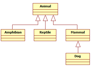
A child class is a specialisation of its parent class
Although we have not explicitly shown any attributes or operations for any of the classes shown here, you should note for future reference that it is unnecessary to display attributes or operations on a child class that have already been specified for a parent class, because the child class will automatically inherit them. You might recall that we have already seen an example of generalisation in the simple bank system class diagram we looked at earlier. Part of that diagram is reproduced below. You can see from the diagram that the classes CurrentAccount and SavingsAccount are both children of the BankAccount class. A class that is used purely as a generalisation from which to derive other (child) classes, and which is not used to create objects (instances) in its own right, is called an abstract class.
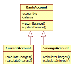
CurrentAccount and SavingsAccount are specialisations of BankAccount
Dependencies
A dependency is a relationship, like an association, but one in which one class depends upon another. You need to be slightly wary here. Think about the class Car for example. It would be natural to think of the Car class being dependent on, say, a class called Wheel. While this is true, the relationship between Car and Wheel would better be described as an aggregation or a composition (these relationships will be described shortly) in which the Wheel class is represented as a component of the Car class. A better example would be the relationship between a car and the fuel it runs on, or the oil that is used to lubricate its engine (you can probably think of other examples), since these things are absolutely necessary for the car to operate but do not constitute part of the car itself. The diagram below illustrates the relationship. Note that the UML indicates a dependency using a dashed line to connect the two classes, with an arrowhead at one end pointing to the class depended upon.
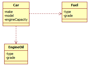
The Car class depends on the Fuel and EngineOil classes
Aggregations and compositions
An aggregation is a special kind of relationship that describes the fairly loose coupling of a number of component classes via some main class. Together, these classes form a collection that constitutes a whole. The whole is represented by the main class, while the parts that belong to it are represented by the component classes, which are connected to the main class via a solid line that has an outline diamond shape at the end nearest the main class. The thing to note about aggregation is that the component classes do not necessarily have to belong exclusively to one particular whole. They may also be part of any number of other collections, and may also have a lifecycle that is different from that of the collection as a whole.
A computer system can be seen as an aggregation because it has many components, some of which may be shared. Your home computer system will typically have a base unit consisting of a case containing a motherboard, power supply unit, disk drives, memory, video graphics adapter, sound card and (of course) one or more central processing unit. It will also have peripheral components such as a visual display unit, keyboard, and mouse. In addition you will probably have a printer attached to the system, and maybe other devices such as a scanner, a webcam, or stereo speakers. Some of these components are dedicated solely to a single system, while others could be shared with (or removed and connected to) another computer system. Virtually any computer peripheral that is not inside the main computer casing can be shared with another computer. It is not uncommon for two computers to share a mouse, keyboard and display unit via a KVM unit, for example. In addition, every component of the computer system can be replaced one or more times during the lifecycle of the system. Here is a class diagram that depicts this situation.
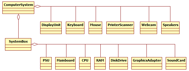
A computer system can be modelled as an aggregation
A composition is very similar to an aggregation in that it is represented by a main class and a number of component classes that together make up a whole. The component classes are connected to the main class via a solid line that has a diamond shape at the end nearest the main class, but this time the diamond shape is filled. The composition can perhaps be described as a stricter kind of relationship in which the entire collection of component classes belongs to just one main class, and the lifecycles of all component classes are coincident with that of the main class. Consider the example of a house. A house might have a living room, a dining room, a kitchen, a bathroom, and one or more bedrooms. We could model the house as a composition for which the main class would be the House class, and component classes would be used to represent the various room types. The diagram below illustrates the concept. A room cannot belong to more than one house, and the lifecycle of the House class will control the lifecycle of its component classes (if the house is demolished, its rooms will cease to exist).

A house can be modelled as a composition
The question of whether a collection of classes constitute a composition or an aggregation is not always easy to decide. As a very general rule of thumb, if the system being modelled is a self-contained physical entity like a car or a building, a composition is usually chosen. If modeling a collection of components that make up something less tangible, such as a software system, an aggregation might be better. A single field in a database that is used to store information about car parts, for example, might contain the part number of a component that is common to many different models of car. The computer system was modelled as an aggregation even though it represents a physical entity because, unlike a car, every single component can be replaced by an identical or upgraded component. Furthermore, many of the computer system's components may be shared with other computer systems, and some components may be removed altogether without rendering the system unusable.
Interfaces
An interface is something that hides the underlying complexity of something while at the same time allowing you to make use of the facilities that it provides. You do not need to understand the workings of the internal combustion engine or the complexities of motor vehicle electronics, for example, in order to operate a car. You do, however, need an appropriate interface through which to access the services these things provide. In a car, that interface is comprised of the steering wheel, gear stick, control pedals, and the various switches and buttons that control the lights, heater, windows and accessories. The same is true of the electrical appliances in your home or place of work. In fact nearly every modern electrical, electronic or mechanical device you can think of has some type of control interface that enables you to use it without needing a degree in engineering.
In the UML, an interface is a set of operations that one class can carry out on behalf of another class. The interface is often modelled using an icon very similar to a class icon. It has no attributes of its own, but defines a set of operations that can be used by other classes. To identify it as an interface on the class diagram, the stereotype notation is used. This consists of the word "interface" enclosed between guillemets (double angle brackets), which appears above the interface name. In the example shown below, the Database class has an interface called dbAccess.
The relationship between a class and its interface is called a realisation, and is denoted by a broken line with an open triangle at the end nearest the interface, pointing at the interface. The realisation is like a contract between the class and its interface, in which the class undertakes to implement the operations defined by the interface. The interface itself does not constitute a class as such, but is somewhat like an abstract class. It cannot be instantiated, and does not implement the operations that it defines. In our example, the Database class is responsible for implementing the operations defined by the dbAccess interface. When a class implements an operation defined by an interface, the implementation must have the same signature as the declaration provided by the interface (that means that it must accept the same number and types of parameters, and return the same return value type).

The Database class must implement the operations defined by the interface
You will note from the diagram that any class wishing to interact with another class via its interface will be connected to the interface via a dependency. This takes the form of a dashed line, with an open arrowhead at the interface end, pointing at the interface. The interface separates the operations that a class is expected to implement from the implementation itself. Other classes wishing to avail themselves of those operations do so via the interface rather than through the class that realises the interface (i.e. that implements the operations). The benefit of this approach is that if the concrete implementation of those operations changes, it should not affect the classes that depend on them, since they always access them indirectly via the interface. Note also that all of the operations defined by an interface have public scope, so that any class can use them.
UML 2.0 introduced an alternative way to represent an interface Instead of a rectangular icon, a simple ball-and-socket symbol is used to represent the interface. In this notation, the interface is named but details of the operations it performs are omitted. The connection between the interface and the class that realises it consists of a solid line from the class to the ball part of the symbol, while the class that depends on the interface is connected in similar fashion to the socket part of the symbol. You should use this representation if the class diagram you are producing does not actually need to show the specific operations provided by the interface.

The ball-and-socket symbol can also be used to represent an interface
