Component Diagrams
A component is a modular part of a computer software system. It represents a group of related classes and other elements that work together within a self-contained logical structure in order to provide some aspect of the system's functionality. Components can be used in the early stages of system design to establish the overall architecture of the system. In the later stages, they facilitate the allocation of work to development teams. The internal details of a component are encapsulated (hidden from view), and the functionality provided by the component is available only via the interfaces it presents to its environment. A sufficiently well-designed component, with a well-defined set of interfaces, can be re-used in other systems where the same subset of functionality is required. It should be possible to replace an existing component with an updated version, providing the interface definitions remain the same, even though the internal implementation of the new version may be quite different.
Components are effectively another way of looking at structured classifiers of the kind we talk about in the page on composite structure diagrams. They can range in size from relatively small (conceivably a single class) to quite large (a major system component known as a subsystem). A component will often contain a number of classes that work together to realise (implement) the component's functionality, and may even consist of some number of (smaller) components. To illustrate the conceptual difference between a component and a class, consider an inventory control system. While modeling the detail of the system we might create a class called StockItem that holds the part number, description and location of an inventory item. At the other end of the scale, we could create a component called InventoryControl that allows us to create new inventory items on the system, allocate inventory items to sales orders, add new supplies to the inventory record, and make inventory control adjustments.
The component icon
The basic component icon is drawn as a rectangle, with the name of the component displayed inside it. To avoid confusing this icon with a class icon (which can look very similar) the component stereotype («component») is usually displayed above the component name. The UML 1.4 component icon may optionally be displayed in the top right-hand corner of the rectangle, either instead of or as well as the component stereotype. The three methods of displaying a component are illustrated below for a component called InventoryCtrl.

Three equivalent ways of drawing the component icon
The black box view of components
A component, by definition, is a self-contained autonomous unit. The so-called "black-box" view of a component shows how it looks from the outside, without revealing anything about its internal structure. This is often the only view we need of a component when we are looking at how it fits into the overall system architecture. The functionality of the component can only be accessed via the interfaces it provides. By the same token, if the component must use the services of another component in order to carry out its duties, it will require the component providing those services to provide a suitable interface. We can show the interfaces that a component provides, and those it requires, in three ways. The first uses the ball-and-socket notation illustrated below. Each provided interface is shown as a circle (the ball), connected to the component icon by a solid line, and labelled with the name of the interface. Each required interface is shown as a half-circle (the socket), also connected to the component icon by a solid line and labelled with the name of the interface.
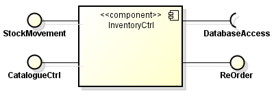
Provided and required interfaces are shown using ball and socket notation
Rather than use ball-and-socket notation, you can show the names of the provided and required interfaces in a separate compartment below the component name, as shown below.
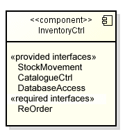
Provided and required interfaces may be listed below the component name
Sometimes it may be necessary to show the signature of a provided or required interface in terms of the operations the interface provides, the arguments that must be passed to those operations, and their return values. If this is the case, the interface can be displayed using classifier rectangles as shown below (note that we have not included operation parameters or return values here to keep the diagram simple). If a component realises (implements) an interface, a dashed line connects the component to the interface icon, with an arrowhead consisting of a hollow triangle pointing to the interface icon. Similarly, if a component requires an interface, a dashed line connects the component to the interface icon, but with an open arrowhead pointing at the interface icon.
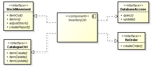
Representation of provided and required interfaces using classifier rectangles
Components and component diagrams
Component diagrams such as the one shown below model the architecture of a software system. They are often referred to by developers as wiring diagrams because they show how components are wired together to create an application, and can help software developers and other stakeholders understand how the larger pieces of the system fit together and communicate. For that reason, the components themselves are often shown on component diagrams as black boxes. A component diagram presents a relatively high-level view of the system, and at this level of abstraction we are not usually concerned with the inner workings of a component. The things that are of interest to us are the dependencies between components, or between components and interfaces.
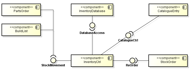
A component diagram models the architecture of a software system
The lines joining components together on the diagram are referred to as connectors, and they indicate that some kind of communication is taking place between the components they connect. Specifically, all of the connectors shown on the above diagram are assembly connectors. An assembly connector uses the ball and socket notation to indicate that one component provides services that are required by another component. Remember that the ball represents a provided interface, while the socket represents a required interface. Note that where two or more components require services provided by the same interface, the connectors can be combined. In the example shown above, the PartsOrder and BuildList components both require the services of the InventoryCtrl component. A similar situation pertains if multiple components provide a particular interface.
Depending on your UML modeling tool, you may or may not be able to represent the dependency relationship between two components on your diagram using the ball-and-socket notation to create an assembly connector. Some tools let you snap the ball and socket symbol together, others require you to insert a dependency arrow between the required and provided interface symbols. You can also simply omit the ball-and-socket notation altogether and just draw a dependency arrow between the components, although using assembly connectors sometimes allows you to show more information about the relationship between the components. The component diagram shown below illustrates the alternative ways of representing the dependency relationship.
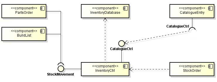
Dependencies can be shown in different ways
A white box view of components
It is sometimes useful to be able to see how the interfaces provided by a component are realised. In order to do this we need to be able to look inside the component to see what elements inside the component (usually classes, but sometimes other components) are responsible for realising each provided interface. We call this view a "white box" view. As with the black box view, there are different ways in which we can show the white box view of a component. One way is to add an additional compartment to the component icon and list the classifiers that realise the component's interfaces, as shown below. The compartment is labelled with the realizations stereotype («realizations»).
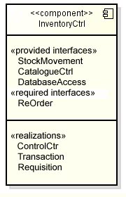
List the classifiers that realise the component's provided interfaces
An additional compartment can also be added to show which artifacts implement the component, as shown below. The artifacts that implement the component are listed beneath the artifact keyword («artifact»). Artifacts are the software elements created by programmers during the actual implementation of the software system. They include data files, executable program files, scripts, and database files. A component (or subsystem) may be implemented by one or more artifacts, which exist on various bits of hardware (network servers, client computers etc.) in the real world. These bits of hardware are referred to as hardware nodes. The disposition of artifacts on hardware nodes is modelled using deployment diagrams (we look at deployment diagrams on another page).
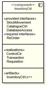
Artifacts may be listed in a separate compartment
The white box view of a component can also be drawn as a structure diagram in which the internal classifiers (or sub-components) are drawn outside of the component icon. The relationship between the component and its internal classifiers is shown using dependencies (see below). The dependency is shown as a dashed line drawn from the classifier or sub-component to the component. An open arrowhead at the component end points to the component.
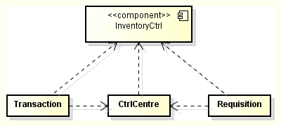
A structure diagram showing component classifiers and dependencies
The classifiers can also be shown inside the component rectangle, as shown below.
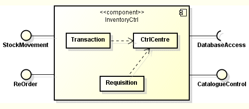
Classifiers can be shown inside the component rectangle
When we model the internal details of a component, we are essentially creating a composite structure diagram in which the internal classifiers are the parts. When you want to show the internal structure of a component (i.e. a white box view), you can link the externally visible provided and required interfaces to the parts that realise or require them via ports. A port represents an interaction point between a component and its environment. It is represented by a small hollow square symbol drawn on the boundary of the component, and may optionally be named. By attaching interfaces to a port, you are indicating that the services provided or required by the component, and defined by the interfaces, are accessed via that port.
A provided interface may be realised by the component itself or by one of the component's public ports, but is more often realised by a classifier within the component. If so, there will be a delegation connector between the port to which the interface is attached, and the classifier that realises the interface. When a request for service arrives at a port on the component, the port delegates the request (via the delegation connector) to whichever internal classifier realises the port's provided interface. The delegation connector is shown as a dashed line from the port to the realising classifier, with an open arrowhead pointing at the classifier, as shown in the example below.

Ports provide interaction points between a component and its environment
If a component has a required interface, the client for that interface is also likely to be one of the component's internal classifiers. If so, any request for service will be sent via a delegation connector to whichever external port the required interface is attached to, with the arrowhead pointing this time towards the port. The port will forward the request to the required interface. In some cases, a port may have both provided and required interfaces attached to it, and is said to be bi-directional.
Sometimes, the parts making up the composite structure of a component have their own ports and associated interfaces. This is often the case where the parts are themselves components within some larger component. In such cases, the delegation connector is normally shown linking an external port with the part's provided or required interface, rather than linking the port directly with the part itself. A component that contains other components may simply represent a larger part of the overall system. At the highest levels of the system architecture, the term subsystem may be used instead of component, in order to indicate that this is an entity that represents a major part of the functionality of the system.
The diagram below shows a subsystem consisting of a number of components. The «subsystem» stereotype replaces the «component» stereotype. Note the use of assembly connectors (the links with the ball-and-socket notation) to connect components internally, and the use of delegation connectors (the dashed lines with an arrowhead at one end) to link component interfaces with external ports.
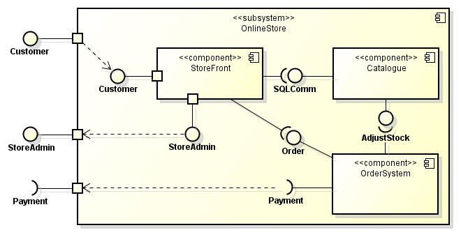
A subsystem consisting of components
Other stereotypes
A number of additional stereotypes not previously mentioned may also be used with components. The names of these stereotypes are listed below, together with a brief description of their meaning.
- «entity» - the component represents some collection of persistent data that represents a business concept
- «implement» - the component has no formal definition itself, but implements a component stereotyped as a «specification» (to which it is related via a dependency)
- «process» - a component that executes a transaction of some kind
- «realization» - a component that has classifiers implementing behavior specified elsewhere (see «specification»)
- «service» - a stateless, functional component that computes a value
- «specification» - specifies a component without defining how it will be implemented (i.e. it has provided and required interfaces but no classifiers)
