Composite Structure Diagrams
Class diagrams can provide us with a lot of generic information about the relationships that exist between classes that work together within complex structures. For example, we can use composition in a class diagram to model the collection of components that make up a self-contained physical entity like a car or a washing machine. Object diagrams, on the other hand, can be used to model specific instances of such a structure. They provide concrete examples of how the structure can be used in order to create a better understanding of the class diagram. Composite structure diagrams go a step further. They allow us to model the interactions that must occur between the internal components of an instance of a structured classifier in order to carry out a specific task.
We should start with some definitions. A classifier describes the structural and behavioural characteristics (i.e. attributes and operations) of a UML element. Examples of classifiers include classes, interfaces, datatypes, subsystems and components. A structured classifier is a classifier whose instantiation results in the creation of a collection of interconnected objects, referred to as its internal structure. The elements that make up this internal structure are known as properties. Properties can be further categorised as parts, which represent specific roles within the internal structure, or connectors. A connector is a link that allows interaction or communication to occur between two or more parts at runtime. Composite structure diagrams are used to model the internal structure of a structured classifier (the containing classifier), and the collaborations that may take place between its parts in order to achieve some common objective.
When an instance of a structured classifier is created, a set of instances corresponding to its properties will also be created (although not necessarily all at the same time). The instance (or instances) created for each property will be an instance of the classifier typing that property. The possibility exists of more than one instance of a property being created, depending on the multiplicity defined for that property for a given instantiation. Note that the method of instantiation used may accept one or more arguments. These arguments can be used to produce variations on the default instantiation. Note also that when an instance of a structured classifier is destroyed, all instances corresponding to parts of that structured classifier are destroyed along with it.
Parts and connectors
To create a structure diagram, the containing classifier is drawn like a normal class icon (but bigger, of course). The icon will have two compartments. In the first, put the name of the containing classifier. The parts that make up the internal structure go into the second, much larger compartment. We created most of the diagrams on this page using the Astah Community UML modeling tool (version 6.5.1). In this software package, the icon used for the containing classifier is called a "Structured Class" icon. The remaining diagrams (those containing collaborations, which we talk about later) were created using Visual Paradigm for UML 8.3 Community Edition, which is free for non-commercial use. Here is the initial structure diagram for a personal computer system.
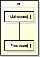
A structure diagram for the structured class PC
The diagram shows that our personal computer has two components - a mainboard represented by a part of type Mainboard, and a processor represented by a part of type Processor. Obviously our model is incomplete at this stage because a personal computer requires several other major components in order to work, but it serves to illustrate the basic features of a simple structure diagram. A part represents one or more instances of a property owned by an instance of the containing classifier. Each part is represented by a rectangle with a solid outline to indicate that the containing classifier exclusively owns that part (a part that is shared with one or more other classifiers is also represented by a rectangle, but the rectangle has a broken outline). The name and type of the part may be shown within the rectangle as follows:
name : classname
The class name and colon may be omitted, which implies that the part is an instance of an unnamed class. In the above example we have omitted part names and shown just the class names (identified as such by the inclusion of a colon to the left of the class name). The multiplicity of each part is shown after the class name inside square brackets (an alternative notation is to place the multiplicity in the top right-hand corner of the rectangle). A generic class diagram for the personal computer system is shown below for comparison purposes.
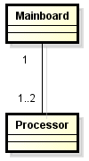
A generic class diagram for the personal computer
The class diagram tells us that an instance of Mainboard can be associated with either one or two instances of Processor. This allows for the possibility of the motherboard being able to accommodate two processors. As such it represents an abstract class, because in the real world, a personal computer mainboard is manufactured either to accommodate one processor or more than one processor. The structure diagram is more specific, because it tells us that there is only one instance of Processor in our personal computer system, and that these parts are linked in some way. We know they are linked because they are joined by a connector, which is represented by a solid line that joins the two parts. The connector represents a logical and/or physical connection between instances of the parts that it connects. A more realistic approach to the class diagram is illustrated below.
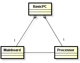
A personal computer system with a single processor
The class diagram now shows the Mainboard and Processor classes as part of a composition in which the main class is called BasicPC. The diagram tells us that our personal computer system contains one mainboard and one processor, and that within the composition the Mainboard and Processor classes have a one-to-one relationship. Let's develop the composite structure diagram further, to include the rest of the major components required for our personal computer system. Here is a list of the components still required:
- Power Supply Unit (PSU)
- Hard Disk Drive (HDD)
- DVD-RW Optical Drive (DVD-RW)
- Memory Module (MM)
We will assume for the moment that the mainboard is of the type that has a sound card and display adapter built in. Here is our updated composite structure diagram:
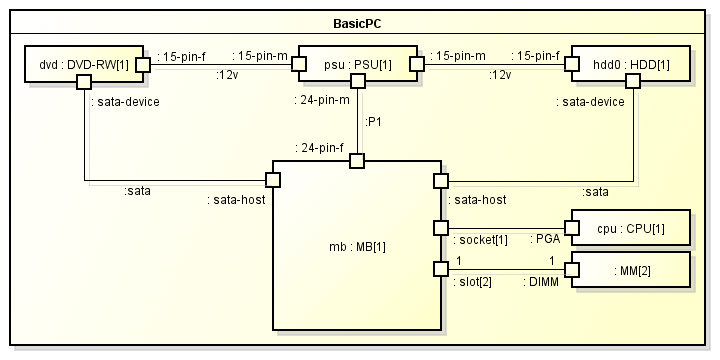
The composite structure diagram now included all of the major components
The composite structure diagram now has all of the major components to be found inside a typical entry-level personal computer, together with the required power, data and control links. Most of the parts have been labelled with both their name and type (the exception is the two memory modules which are not shown separately on the diagram). If you have a working knowledge of how a personal computer is put together, you will not find the diagram too difficult to understand. You will know, for example, that the processor is connected to the mainboard (or motherboard as it is sometimes called) via a socket built into the mainboard. The socket can only accommodate a single physical processor at any one time (which may of course be a multi-core processor, but that is not of concern at the moment).
The computer system has two memory modules, but these have been shown as a single part on the diagram with a multiplicity of two. The memory modules have their own special kind of socket on the motherboard, but because of its elongated shape it is referred to as a slot. Our mainboard has two memory slots, allowing it to accommodate two memory modules. The connector linking the memory modules to the motherboard is shown as having a multiplicity of one at both ends, which implies that there will be two connector instances. The diagram tells us that there will be two instances of MM (the class used to represent a memory module) and two slots.
We have shown the memory slots (and all of the other connection points) using a port (represented by a small square box) that has a multiplicity of two. We will learn more about ports shortly. For the moment, simply be aware that the port to which the memory modules are connected actually represents two separate memory slots, as denoted by its multiplicity. Here is an alternative representation of this arrangement:
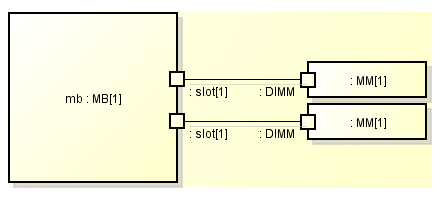
An alternative representation of the mainboard / memory module arrangement
The two slots are now represented by two separate ports. The memory modules are also shown separately, and both the ports and the memory module instances are now named. We chose not to use this arrangement on the original diagram in order to reduce clutter (it is in any case safe to assume that the memory modules are identical). Note that the multiplicities can be omitted, since a multiplicity of one would then be assumed for the ports, memory module instances and connector ends (the multiplicity of a connector end determines the number of connectable elements to which it may be connected).
Note that a connector can either be a runtime instance of an association (as used on a class diagram) or can represent a dynamic link of some kind that is set up at runtime to facilitate communication between parts of a structure. A connector could be created, for example, to enable an operation to be invoked or to facilitate the updating of instance variables. If the multiplicity of a connector end is not shown, it is assumed to have the same multiplicity as the part to which that end of the connector is attached. If the connector end is attached to a port on a part in an internal structure, and no multiplicity is shown, its multiplicity is assumed to be that of the port multiplied by that of the part, if any (ports will be discussed shortly).
The type of communication that may take place over a connector may be subject to constraints, including those that apply to the parts they are connected to (these can be shown using the appropriate notation). The name and type of the connector may be shown in the same way as for a part, using the syntax shown below.
name : classname
Note that it is usually unnecessary to name connections unless they must be uniquely identified for clarity. Our composite structure diagram for the personal computer system shows only the type of the connections representing the power connectors and signal cables connecting the power supply unit, mainboard, optical drive and hard disk. The connectors joining the memory modules and processor ports to the mainboard ports are not labelled at all, since they simply represent the physical interface between the processor and its socket, and between the memory modules and their slots.
Note, incidentally, that the number of ports used in our composite structure diagram for the personal computer system reflects the fact that every component in the system is designed to be upgradeable. Each component therefore connects to one or more other component in the system using a well-defined industry standard interface (which makes it very difficult to accidentally connect two incompatible components together). The concept of ports and interfaces is discussed in more detail below.
Ports
A port, in the context of a composite structure diagram, is any point that serves as an interface between a structured classifier and its environment, between a structured classifier and its parts, or between the parts within a structured classifier. A port is shown as a small square outline on the boundary of a classifier (i.e. a part, a class, or a composite structure), and represents the externally visible part of any instance thereof. The name, type, and multiplicity of the port may optionally be shown near this symbol. A port drawn on the boundary of a structured classifier is public by default. This means it can be accessed by entities outside the classifier. A port drawn completely inside the boundary is protected by default, and can only be accessed by entities within the classifier. You have already seen the port symbol in use on the composite structure diagram for the personal computer system (see above).
A port is usually associated with one or more interfaces. An interface specifies the kind of interactions that can take place over a port. An interface that specifies the services a classifier provides to its environment is called a provided interface. An interface that specifies the behaviour a classifier requires from its environment is called a required interface. External classifiers may access the functionality provided by a classifier through a given port providing they meet the specified behavioural requirements for that port. As an example, consider a hard disk drive in a personal computer system. The drive unit interacts with its environment via two separate interfaces (see below). One is a required interface that allows it to receive electrical power from the power supply unit. The second is a provided interface that allows it to service data storage and data retrieval requests received via the mainboard.
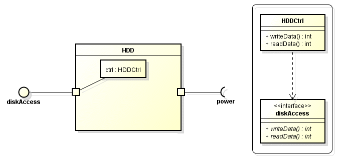
A composite structure diagram for the HDD class
The page entitled "Class Diagrams" gives an example class diagram in which an interface is represented using a class icon. The interface can indeed be modelled as a class, although it will always be an abstract class and cannot be instantiated. The implementation of the interface is down to a concrete class that must implement the functionality specified by the interface. The defined functionality of an interface is exposed (visible to external entities), and any entity wishing to use the services of a structured class via one of its ports can do so by specifying the name of the interface to use, without having to worry about the details of the internal implementation. The abstract nature of an interface specification implies that it may be implemented by any number of classes. Differences between implementations are unimportant, providing each implementation functions as specified.
In composite structure diagrams a more convenient notation, known as ball and socket notation, is normally used to represent an interface. As you can see from the above example, a provided interface is represented as a ball (an outline circle) and a required interface is represented as a socket (a semi-circle). The Interface symbol is connected by a solid line to the port, which is in turn connected to the internal classifier that realises (i.e. implements the functionality of) the interface. In our example we have included an inset showing the class icon for the HDDCtrl class as it would appear on a class diagram, together with the abstract interface that it realises. A port that provides access to the published functionality of an interface implemented by an internal classifier is known as a service port.
If the classifier owning the port realises the functionality of the port itself (rather than the functionality being realised by one of its internal classifiers), the port is referred to as a behavioural port. If this is the case, the port is linked by a connector to a small state symbol inside the classifier to indicate that it is a behavioural port. By default, ports belonging to composite structures are service ports and not behavioural ports. Behavioural ports are sometimes to be found on simple (as opposed to composite) classifiers. We could conceivably model the HDDCtrl class as shown below. The functionality offered by port p is realised by the class HDDCtrl, which realises the diskAccess interface.
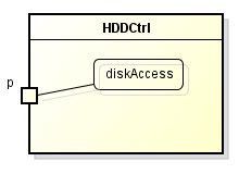
A behavioural port is both owned and realised by the same class
A port may be explicitly typed by showing the name of the port, followed by a colon, followed by the name of the classifier that realises the interface. Alternatively, the ball and socket notation used to denote an interface can be replaced by typing the port using the name of the interface. Examples of both approaches are illustrated below.
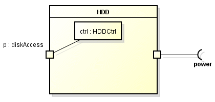
A port can be typed using the name of a class (left) or an interface (right)
A port may also provide multiple interfaces when several distinct but related services may be accessed via the same port. The example below shows each interface represented by a separate interface icon. A single interface may be used to represents all of the interfaces (the name of the port appears near the interface icon and is followed by a colon, followed by a comma separated list of the interfaces associated with the port).

A port may provide multiple interfaces
A classifier may also be associated with multiple ports, enabling different types of interactions to occur depending on the port through which messages are received. The classifier may even implement multiple interfaces.
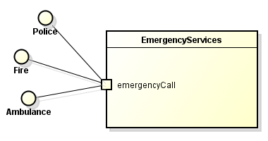
A classifier may realise the interfaces for multiple ports
A port may also be connected with multiple internal elements that realise the same interface, as in the example shown below.
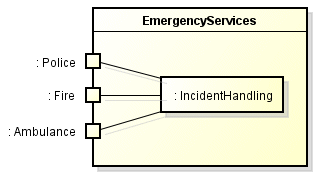
Multiple classifiers may realise the same interface
Collaborations
A collaboration describes how two or more elements within a structured classifier co-operate at runtime in order to carry out a specific task. A collaboration diagram represents the collaboration as a dashed ellipse, with the name of the collaboration inside it, as shown below. The roles involved in the collaboration may be drawn within a separate compartment inside the ellipse, with the connections between them shown using a solid line. Each role is drawn as a rectangular icon, with the name of the role shown inside the icon. Roles may only be played by elements within the structured classifier that owns the collaboration. Each element playing a role in a collaboration becomes a property of that collaboration. The connections between the roles played by elements must be matched by a corresponding connection between those elements within the structured classifier.
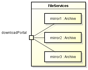
Sale is a collaboration between two roles - Buyer and Seller
The abstract nature of a collaboration means that it cannot be directly instantiated. In fact, it is possible for a role to be played by more than one element within a structured classifier. It is also possible for a given element to play different roles in different collaborations owned by the structured classifier. Since the purpose of a collaboration diagram is usually to describe some specific aspect of the functionality of a structured class, unnecessary details can be omitted, as can the precise identity or class of participating instances. The functionality offered by a structured classifier to its environment is often defined by the interfaces it presents to that environment. A collaboration can selectively focus on just one of those interfaces, and ignore any internal elements that are not involved in the functionality that it provides.
The association of a collaboration with a structured classifier is called a collaboration occurrence, and indicates that the collaboration represents some aspect of the functionality of that classifier. A collaboration occurrence is shown on a composite structure diagram using a dashed ellipse, as illustrated below. The name of the collaboration follows the name of the occurrence, with the two names being separated by a colon. A dashed line is drawn from the occurrence to a classifier icon, with an arrowhead pointing at the classifier to indicate that the collaboration is used by the classifier. The line is labelled with the keyword «occurrence».
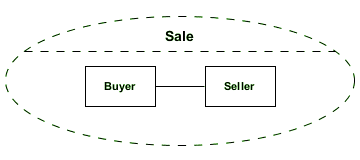
The collaboration Sale is used in the Distribution classifier
The same notation is used to indicate that the collaboration represents the classifier, except that the keyword used is «represents».

The collaboration Sale represents the Distribution classifier
The term collaboration use is used to describe the application of a collaboration to a specific situation, with specific classes or instances playing the various roles. Each role in the collaboration is referred to as a supplier. Each element that plays a role is referred to as a client. A collaboration use binds the client elements within a structured classifier to supplier roles in a collaboration. The relationship created between the roles and the elements that play them is called a role binding. All of the client elements must belong to the same structured classifier, and all of the supplier elements must belong to the same collaboration.
A collaboration use is shown as a dashed ellipse, inside which the name of the collaboration occurrence is followed by the name of the collaboration type, with a colon separating the two. Each client element involved in the collaboration is shown in its own rectangular icon outside the ellipse. The role binding is shown as a dashed line from the ellipse to the client element, labelled at the client end with the name of the supplier element. Multiple occurrences of a given collaboration may apply to a structured classifier, each involving a different set of roles and connectors. By the same token, the same role or connector may be involved in multiple occurrences of a collaboration, or a number of different collaborations. Above, we showed an occurrence of the Sale collaboration as belonging to a structured classifier called Distribution. This is what the Distribution composite structure diagram might look like:
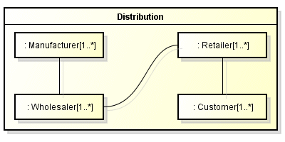
A composite structure diagram for Distribution
We could create a collaboration use of the Sale collaboration involving the Wholesaler and Retailer properties of Distribution as shown below (you should be able to identify two other scenarios for which a collaboration use could be created).
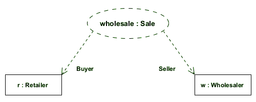
The wholesale collaboration use of the Sale collaboration
It is quite acceptable to use one collaboration within the definition of another collaboration. Looking at the Distribution structured classifier, it can be seen that a sale of some kind may occur at three levels. The entire supply chain, from manufacturer to retail customer, can be modelled as a collaboration between all of the entities represented by the Distribution classifier. The wholesaler buys goods direct from the manufacturer and sells them to the retailer, who in turn sells to the retail customer. Buying and selling thus occurs at three levels in the supply chain. We can model this scenario using the SupplyChain collaboration shown below. You can see from the diagram that the Sale collaboration is used three times for the definition of the SupplyChain collaboration. The roles of Buyer and Seller are played by different clients at each level in the supply chain model.
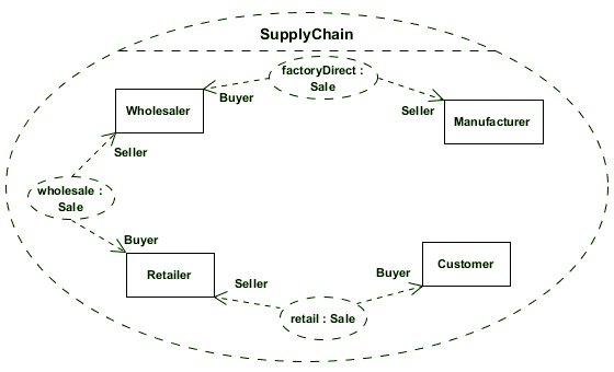
The SupplyChain collaboration
