Deployment Diagrams
A deployment diagram can be used to model the physical architecture and (in the case of networks or distributed systems) the topology of the software system being developed. It describes the hardware devices (known as nodes), the software components that run on them (known as artifacts), and the communication links between the various nodes and artifacts. In the most trivial case, the "system" may consist of a single executable (.exe) file that runs on a stand-alone computer. The illustration below shows what such a scenario might look like as a deployment diagram. The Organiser.exe artifact represents a single instance of an executable program file, is deployed to the DesktopPC node, which represents a stand-alone desktop computer.
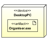
The Organiser.exe artifact is deployed on the DesktopPC node
Creating a deployment diagram for a system that consists of a single node is probably somewhat superfluous. If you have a system for which artifacts will be deployed on a number of hardware nodes, however, the deployment diagram can be used as a blueprint for installing your system. It can also be of great help when discussing physical system layout with various stakeholders. Indeed, as mentioned above, deployment diagrams may be used to model both local networks and distributed systems. At the other end of the scale, deployment diagrams can also be used to model the architecture of embedded systems. The deployment diagrams on this page were created using Visual Paradigm for UML Community Edition, which is free for non-commercial use.
Nodes
An artifact icon is drawn inside a node icon to show that the artifact is deployed on that node. The node itself thus becomes the deployment target for the artifact. Note that the node DesktopPC is labeled with the stereotype «device» (to indicate that this is a hardware node), and the name of the node. A node is represented as a cube, presumably because the use of a three-dimensional shape emphasizes the fact that the node represents some physical object in the real world (i.e. an item of hardware). Note, however, that a node can also be used to represent a software environment that hosts an artifact. Examples of hardware nodes include desktop computers, workstations, servers, disk drives, and embedded hardware such as microcontrollers.
Two alternative methods of showing a deployment are illustrated below. In the first, an artifact is shown as being deployed to a node by placing the artifact outside of the node, and drawing a dependency between the artifact and the node (represented as a dashed line drawn from the artifact to the node, with an open arrowhead pointing at the node). The stereotype «deploy» is used to emphasise the relationship. The second method allows a more compact representation in which the deployed artifacts are simply listed inside the deployment node (this is useful if you have a large number of artifacts deployed on a single node). Note however that this form of representation does not allow any dependencies between artifacts to be shown on the diagram.

A deployment can be shown using a dependency
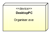
Deployed artifacts may simply be listed within the deployment target node
Examples of software nodes could include operating systems, web server software such as Apache or Microsoft's Internet Information Server (IIS), or the Java Runtime Environment (JRE). If the node represents a software environment, the stereotype «device» is replaced by the stereotype «execution environment». The execution environment must itself run on a piece of hardware of some kind, so it is common to see a software node nested within a hardware node on a deployment diagram, as shown below. In this case, the execution environment consists of an Apache HTTP server running on a Linux server (a scenario quite commonly encountered in commercial web hosting environments).
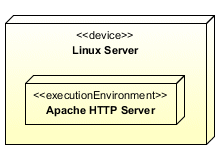
A software node may be nested within a hardware node
The execution environment can also be shown outside of the hardware node, with a composition arrow linking it back to the hardware node (note that the same notations can be used to model a nested hardware node, such as a graphics card or a hard disk drive inside a computer). The relationship between the device Linux Server and the execution environment Apache HTTP Server could be modeled as shown below. Note that the UML specification encourages users to define their own stereotypes for standard execution environments. The examples given in the UML Superstructure document include «OS», «database system», and «J2EE container». These stereotypes could be defined in a profile (see the page on profile diagrams).
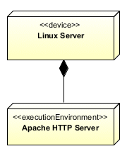
A composition relationship between a nested node and its host
The services provided by an execution environment are usually implicit in the stereotype used, but the UML Superstructure document states that an execution environment may optionally have "an explicit interface of system level services that can be called by the deployed services". Examples of how this interface might be expressed are not provided, but the services could perhaps simply be listed in a separate compartment within the execution environment node's icon.
Just as an execution environment (or another hardware node) can be nested within a hardware node, so can one execution environment be nested within another. In the diagram below, for example, the «web server» execution environment is nested within the «OS» execution environment (note that in both of the execution environment nodes, the «execution environment» stereotype has been substituted by an application-specific stereotype).
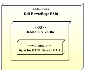
One execution environment can be nested within another
The relationship between deployment targets and deployed artifacts can be defined at the type level (in which a generic node or artifact may be used to represent one or more instances) or at the instance level (in which case the node or artifact represents a specific instance). The UML Superstructure document suggests underlining the name of nodes and artifacts to indicate an instance, although this is optional, since the context will usually make it obvious what is intended. In the example above, the device node could represent any number of Dell PowerEdge servers, each running the Linux operating system and playing host to Apache web server software. The example below shows a specific instance of Apache running over a specific instance of Linux installed on a specific server called WebServer1.
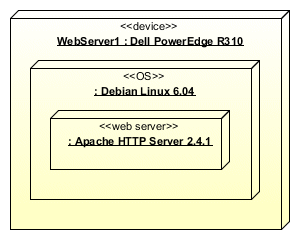
Nested node instances
Clearly then, a deployment diagram could have two or more nodes of the same type. In a commercial web hosting environment, for example, we could have multiple servers of the same type. In order to show that they are different instances, use the notation shown above, in which the type of the node is preceded by the name of the node, with a colon separating them like this:
name : type
Note that the name of a node instance may be omitted from a deployment diagram if its inclusion serves no useful purpose. The deployment diagram below shows a (greatly simplified) view of a web server farm consisting of three servers. In theory, since a node is a specialization of a class, attributes could be assigned to a node, but there is no indication in the UML Superstructure document that this is the case. There is no support for adding them in the UML modeling tools we have tried. If the user wishes to include additional information about a node within the deployment diagram, they could perhaps attach a note.
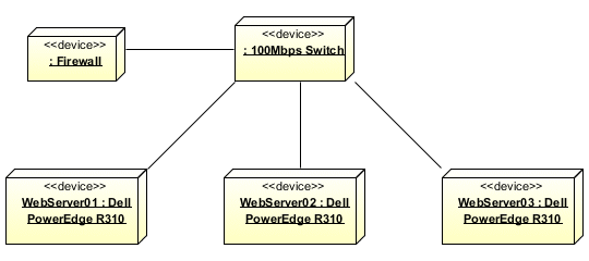
A web server farm deployment diagram
Artifacts
An artifact is deployed on a node (the deployment target), and is typically the compiled version of a component (i.e. an executable file), but it can also be a script, a library file, a database file, a configuration file, or a text file. In fact it can be any kind of file that forms part of, or is used by, your application. If the artifact represents the physical implementation of a packageable element such as a component, it is said to manifest that element. Since just about any type of UML element is packageable, an artifact can manifest just about any UML element.
An artifact is usually shown as a rectangle, with the «artifact» stereotype and the name of the artifact inside it, and a small document icon in the upper right-hand corner. The artifact may alternatively be depicted as an icon. The example below shows the artifact InventoryCtrl.exe manifesting the component InventoryCtrl. A manifestation relationship is shown using a dependency arrow. This is shown as a dashed line from the artifact to the component (or other packageable element) that it manifests, with an open arrowhead pointing at the component. The stereotype «manifest» is shown in close proximity to the line.

The artifact InventoryCtrl.exe manifests the component InventoryCtrl
Note that linking artifacts to the packageable elements they manifest and to the deployment targets on which they are deployed can produce a somewhat cluttered deployment diagram. For this reason, manifestations are either shown separately on the deployment diagram, or on a separate diagram. They are commonly shown on component diagrams by listing the artifacts that manifest a component in a separate compartment within the component's rectangle. Note also that the name of the artifact does not necessarily have to be the same as the name of the packageable element that it manifests (although the names are often similar).
In cases where more than one artifact is deployed to a deployment target, or even in cases where artifacts are deployed to different deployment targets, there may be a dependency between one artifact and another (i.e. one artifact relies on services provided by another artifact). This dependency is shown in the normal manner (see below), using a dependency arrow from the artifact that requires the services to the artifact that provides them.
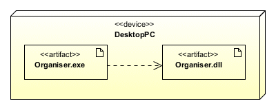
The Organiser.exe artifact depends on the Organiser.dll artifact
This seems like a good time to mention that a number of standard stereotypes are defined by the UML specification that can be applied to artifacts. Examples include «source» (to represent a file consisting of program source code), «executable» (to represent a compiled program file that can be executed by a computer), and «library» (to represent a file containing library routines that may be called by a program). The diagram below illustrates the use of standard UML stereotypes. Note that the standard stereotypes may be further specialised (using a profile) in order to reflect a particular target platform or application environment.
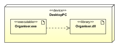
Standard UML artifact stereotypes include «executable» and «library»
When an artifact is deployed to a specific hardware node or execution environment it becomes an instance. A stand-alone application may be deployed to a number of different desktop computers in an office, each copy representing an instance of the original artifact. An instance is indicated by underlining the name of the artifact, as shown below. Note that the UML Superstructure document states that the underlining may be omitted if it is obvious from the context of the deployment diagram that the artifact is an instance, although most UML modeling tools underline the names of artifact instances anyway.
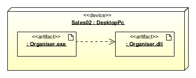
Artifact instances deployed on a hardware node
Artifacts can also be linked by composition associations. In the example below, the artifact inventory_ctrl.ear contains the artifact inventory_ctrl.jar and the deployment specification application.xml (a deployment specification is a specialised kind of artifact, which we will describe shortly). A composition is shown using a solid line that connects the contained artifact to the container artifact, with a solid diamond shape at the end nearest the containing artifact. For those unfamiliar with Java, the .ear (Enterprise Archive) file format is used to package one or more .jar (Java Archive) files for ease of deployment onto an application server. The archived files will normally include the application.xml file, which is the deployment descriptor (covered below) for an Enterprise application.
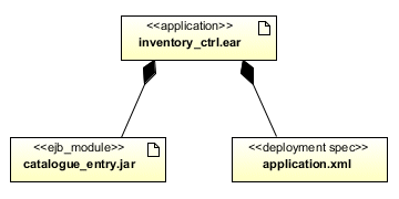
Artifacts can have composition associations
Artifacts can also have properties that represent features of the artifact, and operations that can be performed on their instances. The properties of an artifact usually represent some set of configurable options. For that reason they are most often to be found in a deployment specification (see below), the purpose of which is to define the configuration settings for a deployed artifact. You can list the properties of an artifact in a separate compartment below the artifact's name.
Communication paths
Nodes may be connected to other nodes via associations that represent communication paths, indicating that communication may take place between the nodes. A communication path may exist, for example, between a hardware node representing an application server and another hardware node that represents a client workstation. A communication path is drawn as a solid line connecting two nodes. The type of communication being modeled can be shown using an appropriate stereotype. In the example below, the model describes a desktop computer communicating with an intranet server over an Ethernet connection. Note, however, that communication paths can also represent wireless connections. We can use hardware nodes and the communication paths between them to model the topology of a network.

A communication path stereotyped as an Ethernet connection
A communication path can also be used to show that communication may take place between execution environment nodes. The stereotype used for a communication path should reflect the type of communication we are interested in modeling. In the example below, the association is stereotyped as a TCP/IP connection. Although the data will obviously be transmitted via some physical transmission medium, such as an Ethernet connection, we are interested here in the communication between two execution environments. In this case, the execution environments happen to be a web browser and a web server, which requires the use of the TCP/IP protocols.

A communication path between execution environment nodes
Deployment specifications
A deployment specification is a special kind of artifact that specifies the parameters to be used by another artifact (usually an executable file or script) at run time, either to determine how the artifact runs, or to configure the artifact's host (i.e. a hardware node or execution environment). The deployment specification is typically deployed to a node along with the artifact whose runtime parameters it describes. The deployment specification is drawn as a rectangle, as shown below, and looks like any other artifact except that the «artifact» stereotype is replaced by the «deployment spec» stereotype. In addition, the rectangle may optionally have an additional compartment in which the deployment specification's properties are listed. The properties are listed using the name : type notation:
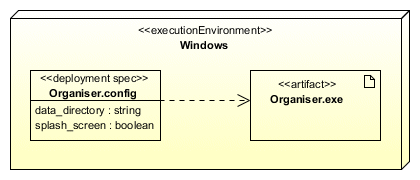
A deployment specification parameterises an artifact
In the above example, both the artifact Organiser.exe and the deployment specification Organiser.config are deployed to the execution environment Windows. The deployment specification is connected to the artifact it parameterises using a dependency arrow (a broken line from the deployment specification to the artifact, with an open arrowhead pointing at the artifact). Both the artifact and the deployment specification are nested within the execution environment. The deployment may alternatively be modelled as shown below, with the artifact connected to the execution environment using a deployment arrow. The deployment specification is attached to the deployment arrow via a broken line.
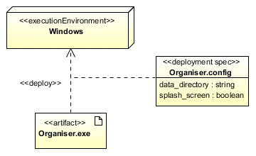
The deployment specification may be attached to the deployment arrow
Like an artifact, a deployment specification becomes an instance when deployed to a specific host environment. An instance of a deployment specification is called a deployment descriptor. The name of the deployment specification will be underlined, and the deployment properties will be given specific values, as shown below. In this example, an instance of the Organiser.exe artifact is deployed to a desktop computer running the Windows operating system, and is parameterized by an instance of the deployment specification Organiser.config.
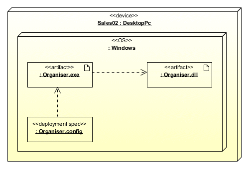
Deployment descriptor properties have specific values
