Package Diagrams
Let's suppose we have been tasked with modeling a college management system for a large municipal college. As well as its various faculties, the college will have a complex support infrastructure. One of the functional areas we are investigating is the Estates department, which among other things is responsible for managing and maintaining college buildings and other facilities. We have identified a number of classes related to the physical infrastructure of the college. These include the classes Office, Classroom and Workshop, which store attributes and operations related to various types of accommodation within the college. The illustration below shows a couple of ways in which we might draw a package to represent the Estates department. Incidentally, the package diagrams on this page were created with the Astah Community UML modeling tool, a free educational edition.

Two representations of the Estates package
The icon for a package is a tabbed rectangle that looks like the folder icon used in popular computer desktop operating systems. There are at least two ways of drawing package icons, as you can see, depending on the features of your UML modeling tool. In the representation on the left, the contents of the package are not shown, and the name of the package is displayed in the body of the package icon. In the representation on the right, the contents of the package (or a subset thereof) are included within the body of the package icon, and the name of the package is moved into the package icon's tab. Note that the naming convention for packages is the same as that for classes. Names start with an upper-case letter, and if the package name consists of more than one word, each new word also starts with an upper-case character.
Everything inside a package shares the same namespace, and must have a unique name. If a package element is referenced from outside the package, its fully-qualified name should be used. This will consist of the name of the package, followed by a double colon ("::"), followed by the name of the package element. For example, if we wanted to access the Workshop class in the Estates package, we would have to refer to it by its fully-qualified name, which is Estates::Workshop. The visibility of elements inside a package can be specified as either public or private. If an element has public visibility, it can be accessed by UML elements outside the package (providing the fully-qualified name is used to reference it). If the element has private visibility, only UML elements inside the package may access it, but they can do so without having to use the fully qualified name.
We said earlier that packages can contain other packages. As we uncover more information about the functional responsibilities of the Estates department, we find that there is much more going on here than we at first thought. Accommodation is only one area that the Estates department is responsible for. Others include parking for staff and visitors, site security, utilities (lighting, heating, water and sanitary facilities), maintenance, procurement (materials, equipment and services) and health and safety. Once we have gathered all of the required information together, it turns out that we have a significant number of classes for the Estates department that should probably be organised into a number of smaller packages. You can see the revised Estates package below. This is probably as good a time as any to point out that, as the analysis proceeds, your model will inevitably change and grow. This is a natural process that reflects the improvement in your understanding of the system requirements as you accumulate data.
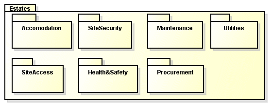
The Estates package is now composed of a number of sub-packages
Using package diagrams allows you to create a layered model that reflects the structural or functional hierarchy of the system under investigation (or part thereof). A package may include both sub-packages and classes. If a package contains only sub-packages, it can be referred to as a domain. In the above diagram, the Estates package is a domain because it contains only sub-packages. The relationship between a domain and its sub-packages can optionally be shown as a tree structure, using a line drawn between the domain and its elements with the nested class symbol (a circle with a "plus" sign inscribed within it) at the domain end, as shown below. This might be preferable if you want to show the relationships that exist between the sub-packages.
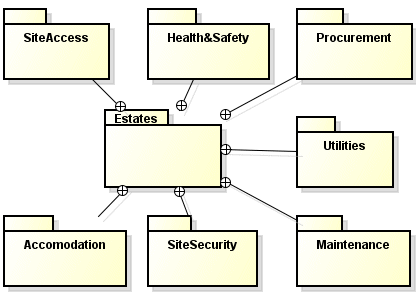
A package with sub-packages can be displayed as a tree structure
Each connection between a domain and a sub-class is conceptually similar to the connections used on a class diagram to connect the main class in a composition with its component classes (these connections are drawn using a solid line with a filled diamond shape at the end nearest the main class). Another kind of relationship that can be shown on a package diagram is a dependency. A dependency is indicated by a broken line connecting two packages, with an open arrowhead at the end nearest (and pointing to) the package being depended upon. This allows us to visualise how the various packages that make up a system or sub-system depend upon one another.
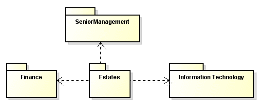
The Estates package is dependent on Finance, InformationTechnology and SeniorManagement
According to most interpretations of the UML specification, a dependency is a directed relationship that indicates that one UML element (or set of elements) depends on another UML element (or set of elements) for its specification or implementation. A dependency is sometimes referred to as a client-supplier relationship in which the supplier provides something to the client. In the example provided above, we are interested in showing which other departments within the college the Estates department depends upon in order to be able to function. The IT department will provide IT services (as it will to every department in the college) and the Finance department will allocate funds for the procurement of materials, equipment and services. Senior management will oversee all major decisions, and will determine policy.
Our diagram shows part of the system at a very high level of abstraction, and depicts the Estates package as the client for three supplier packages (SeniorManagement, Finance, and InformationTechnology). Note that we could also show dependencies that work in the opposite direction, since many departments within the college rely on the Estates department for various site services. The IT department will rely on floor plans and other site information held by the Estates department, for example, when it plans the deployment of computer equipment or needs to make changes to network cabling. The type of dependency involved can be specified by the inclusion of one of several standard UML stereotype keywords above the dependency arrow. For example, one of the stereotypes defined for dependency is «usage», which indicates that the supplier is used in some way for the definition or implementation of the client. We have avoided the use of stereotypes here, as they are probably more meaningful at a lower level of abstraction.
There are two special kinds of dependency between packages that you should be aware of. The first is called a package import, and defines a relationship in which one package (the importing package) adds the names of the elements in another package (the imported package) to its own namespace. A dependency is signified as a package import by adding the «import» stereotype keyword above the dashed dependency arrow. In fact by default, an unlabelled dependency between two packages is interpreted as a package import relationship. The package diagram below illustrates the concept.
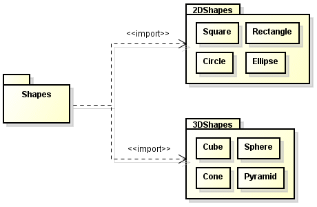
The Shapes package imports the 2Dshapes and 3Dshapes packages
The Shapes package imports both the 2dShapes package and the 3Dshapes package. Elements within the Shapes package may now access the elements of the other two packages using their unqualified names. Note that, by default, the visibility of imported elements is public (i.e. they can be accessed from outside the importing package). If the visibility of the imported elements is required to be private (making them accessible only to elements within the importing package), then the keyword «access» should replace the keyword «import» on the diagram.
Note that package import creates a potential for name conflicts to arise. In the event of an imported element having the same name as an element that already exists in the importing package, the pre-existing element takes precedence, and the imported element can only be reference from within the importing package using its fully qualified name. Individual elements of a package can also be imported into another package in a similar process called an element import. This works in more or less the same way as a package import, except that instead of one package adding every element of another package to its namespace, only the selected element is added (in order to deal with naming conflicts, an alias can be specified for the imported element). The dependency arrow connects the importing package to the imported element, rather than to its parent package.
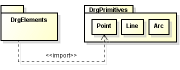
The DrgElements package imports the Point class from the DrgPrimitives package
The second special kind of dependency that you should be aware of is called a package merge. When one package (the source package) merges another package (the target package), the source package is extended by the elements in the target package. In other words, the characteristics of the target package are added to those of the source package, so that the source package essentially becomes a combination of both packages. This mechanism is useful when elements in both packages have the same name and perform a similar role. The process is much like that of generalisation (the UML term for inheritance) in the sense that a base package may be enhanced by adding the contents of another (related) package in which elements common to both packages have been enhanced in some way, or to which new capabilities (in the shape of new elements) have been added. Package merges can be carried out incrementally in order to tailor a source package for a specific purpose.
If a package merge occurs in which a class in the target package has the same name as a class in the source package, then the imported class will automatically extend (or generalise) the class in the source package. Classes that exist only in the target package are simply added to the source package, and classes that exist only in the source package remain unchanged. If the target package contains sub-packages, these are also added to the source package (if a sub-package in a target package has the same name as a sub-package in the source package, a separate merge process occurs between the sub-packages). In the illustration below, the 3Dshapes package merges the Polyhedra package. It will be extended by acquiring the Dodecahedron, Tetrahedron, Octahedron and Icosahedron classes. The Cube class in the source package (3Dshapes) will be extended (or generalised) by the Cube class in the target package (Polyhedra).
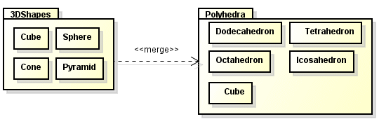
The 3DShapes package merges the Polyhedra package
A dependency is signified as a package merge by adding the «merge» stereotype keyword above the dashed dependency arrow. The effect of the merge on package 3Dshapes can be seen below. New classes Dodecahedron, Tetrahedron, Octahedron and Icosahedron are created in 3dShapes that inherit all the characteristics of their counterparts in the Polyhedra package. The existing Cube class in the 3Dshapes package inherits the features of (is generalised by) the Cube class from the Polyhedra package. The target package itself is unaffected by the merge operation.
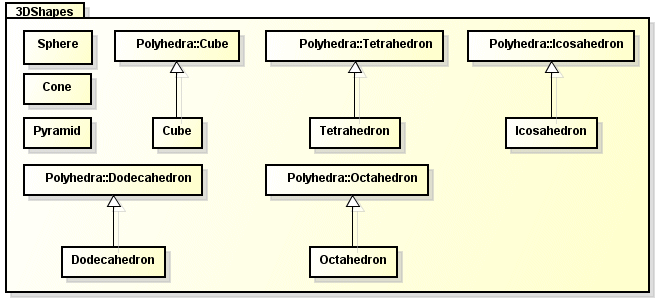
The 3DShapes package merges the Polyhedra package
We mentioned earlier that packages are often used to group together the use cases on use case diagrams in order to illustrate some aspect of the functionality of a software system at a higher level of abstraction. The package diagrams we have looked at on this page have not included examples of packages being used in this way, because we will be covering this topic on the page dealing with use case diagrams.
