Use Case Diagrams
The use case diagram (the word "use" is pronounced as a noun in this context, and not as a verb) is one of the UML'S behaviour diagrams. The primary purpose of a use case diagram is to describe the behaviour of a system from the user's point of view. It describes what the system does (i.e. its functionality), not how it does it. For this reason, the creation of use case diagrams often forms part of the requirements gathering process. The elements of a use case diagram include:
- use cases - specific pieces of the system's functionality
- actors - people or things that interact with the system's use cases
- associations - used to link actors with the use cases they interact with
- system boundary - defines what functionality is included within the system
The simplicity of the notation used for use case diagrams (see illustration below), together with the fact that they describe interactions between a system and the users of that system from the user's point of view, means that they provide a useful point of reference in discussions between developers and clients. Many of the actors and use cases will be identified during initial interviews with the client, and with the end users of the proposed system. Some will emerge later, during the detailed analysis and requirements gathering process. The use cases that are identified will determine the scope of the system (i.e. the complete range of functionality that the system is expected to provide).
The uses cases are normally accompanied by more detailed documentation that describes the expected behaviour of a use case, the conditions that must be satisfied in order for the expected outcome to be achieved, and the action to be taken in the event that one or more of those conditions cannot be met. This makes use cases useful to developers when identifying specific test cases for testing the system. It also helps them to outline the flow of logic when designing the program. Since use cases describe the system from the user's point of view, they can also suggest features that should be included when designing the user interface and user documentation.
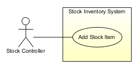
A simple use case diagram
Use cases
The primary feature of a use case diagram is the use case itself, which represents a particular piece of the system's overall functionality. In fact, the functionality of the entire system, from the user's point of view, can be captured as a set of use cases. Each use case represents a specific set of actions that the system (referred to in the UML Superstructure document in this context as the subject) may be required to carry out, in collaboration with one or more external entities called actors. In its most basic form, a use case is represented as an ellipse, with the name of the use case either underneath it or inside it, as shown below. Alternatively, it may be represented using a standard rectangular classifier icon, with a small ellipse displayed in the top right hand corner. Note that the name of a use case usually consists of a combination of verbs and nouns that describes, in a concise manner, the required functionality. Note also that the order in which the use cases appear in a use case diagram is not significant.
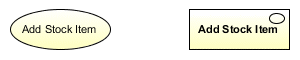
A use case may be represented as an ellipse or a rectangle
Strictly speaking (according to the UML Superstructure document) the term use case refers to a use case type, whereas an instance of a use case would refer to the actual occurrence of behaviour conforming to one of the scenarios described in the use case description (more about that particular document later). As such, an instance of a use case may be described in one of the UML's interaction diagrams.
Actors
A use case is always associated with one or more actors. The execution of a use case is initiated by an actor, and upon completion the use case must return a result to an actor (either the actor that initiated the use case, or another actor). The actor is an external entity, and not part of the system as such. It represents a role played by a person (e.g. a user), another system, or some other external entity. It could even be the passage of an interval of time, or the occurrence of a specific time or date. Note that the same actor may be involved in multiple use cases, and may initiate multiple use cases either at the same time or at different times. An actor is usually represented by a stick figure, especially if the actor represents a human entity (such as a user). Alternatively, the classifier rectangle may be used (typically for non-human actors). A graphic icon may also be used to represent specific types of non-human actor. If a stick figure or graphic icon is used, the name of the actor appears below the icon. If the classifier rectangle is used, the name appears inside the rectangle, with the stereotype «actor» displayed above it.
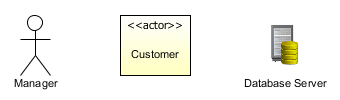
An actor may be represented as a stick man, a classifier rectangle or a graphic icon
Associations
An association between an actor and a use case indicates either that the actor initiates the use case, or that the actor receives the results of executing a use case, or both. The association is drawn as a solid line. The convention is to place an actor that initiates a use case on the left of the use case, while an actor that receives the results of a use case appears on the right of the use case. The illustration below shows a typical scenario. The Stock Controller actor initiates the Add Stock Item use case. If the use case is executed successfully, details of the new stock item will be added to the inventory database, which is represented by the Inventory Database actor.
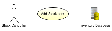
The Stock Controller actor initiates the Add Stock Item use case
Remember that the association represents communication between an actor and a use case (i.e. that the actor participates in the use case), but does not imply the direction in which communication flows. Positioning an actor on the left-hand side of a use case only implies that the actor initiates the use case (i.e. causes it to start executing). Thereafter, communication may flow in either direction. Consider the use case diagram below, which is a simplified representation of a medical practice. The Patient actor initiates the Make Appointment use case (either by telephone or by calling at the surgery in person). The Receptionist actor will check for the first available appointment, and inform the Patient actor of the time and date. If the Patient actor is happy with the appointment offered, they will signify their acceptance. The appointment will then be entered onto the system.
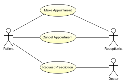
A simplified representation of a medical practice
The purpose of an association between an actor and a use case is only to show that the actor participates in the use case. Detailed information concerning the nature of the interactions that occur between a use case and the actors that participate in it will be contained within the use case description. The use case description is a separate document (usually a text document).
If required, multiplicity can be shown at either end of an association. In the diagram below, you can clearly see that an instance of the Withdraw Cash use case may be initiated by one instance, and only one instance, of the Customer actor. Conversely, the Customer actor may initiate zero or one instances of the Withdraw Cash use case. Note that if the multiplicity at the actor end of an association is greater than one, and it is clear from the context that the actor initiates the use case, this would indicate that more than one actor is involved in initiating the use case. The required actions occur either concurrently (i.e. at the same time), or in sequence (each actor carries out the action required from them in turn).
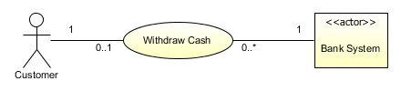
Each end of an association may display multiplicity
The system boundary
The system boundary may be represented as a rectangle that fully encloses all of the use cases shown on a use case diagram. Showing the system boundary in this way serves to represent graphically the scope of the system (or subsystem) being modelled. The actors appear outside the rectangle to indicate that they are not part of the system. Any external entity that interacts with the system, including another system, is an actor by definition. The name of the system or subsystem is usually shown inside the rectangle at the top, preceded by the stereotype «system» (or «subsystem»).
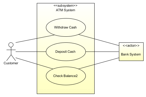
All of the use cases are enclosed within the rectangle representing the system
Sometimes a high-level view of the system may be depicted using just the system rectangle, devoid of use cases but with all of the actors present. This top-level use case diagram is somewhat similar to the context diagram (a top level data flow diagram) used in some systems analysis methodologies. Indeed, its only real purpose is to define the domain of the system in very broad terms, and put it into some kind of context. An example is provided below.
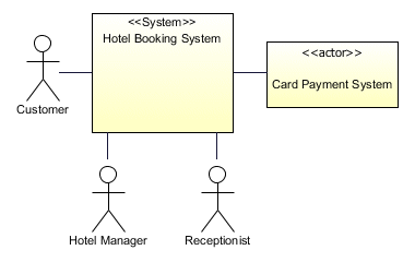
A top-level use case diagram shows only the system and the actors
Extending a use case
An extended use case is one whose behavior is extended by the behavior of another use case (the extending use case). The extended (or base) use case is a complete use case in its own right, as is the extending use case (although the extending use case will typically be somewhat narrower in scope, and may not be particularly meaningful in isolation). The extending use case does however define a modular set of behavior increments that may be used to extend more than one base use case. The functionality embodied in a use case extension often represents optional behavior that is only called upon when certain conditions are met. The relationship between a base use case and a use case that extends it (see below) is shown using a dashed line connecting the extended use case to the base use case, with an open arrowhead pointing at the base use case. The line is labeled with the «extend» stereotype.
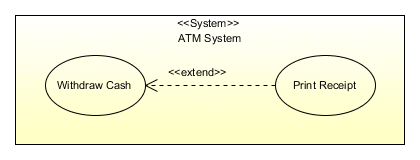
The Print Receipt use case extends the Withdraw Cash use case
In the above example, the subject is an ATM system in which the Withdraw Cash use case is extended by the Print Receipt use case. At some point in the execution of the Withdraw Cash use case occurrence, the customer will be offered the option of printing a receipt. If the customer selects this option, the Print Receipt use case will execute, after which the Withdraw Cash use case will continue from the point where it left off. The point in the behaviour of a base use case at which it may be extended by the behaviour of another use case is called an extension point. Extension points may be listed in a separate compartment within the use case ellipse or classifier icon under the heading extension points, as shown below.
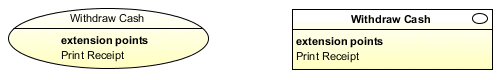
Extension points are shown in a separate compartment within the use case icon
The UML Superstructure document suggests that the name of an extension point could be accompanied by a brief explanation (or formal definition) of where the extension point occurs within the behaviour of the base use case. The Superstructure document does not, however, offer any suggestions as to how this should be formatted. Indeed, it is rather vague about the definition of the extension point itself, citing the reason that "use cases are typically specified in various idiosyncratic formats". It is probably better to put this kind of information into the use case description (see above), where it can be expressed in terms that are appropriate for the chosen development methodology and programming language. On a somewhat more positive note, the Superstructure document suggests that the name of the extension point, together with the condition that must be met in order for the extended use case to be executed, may be displayed in a note attached to the extend relationship.
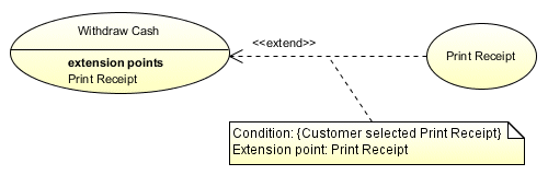
The extension point and its associated condition may be attached to the extend relationship
To describe this situation from a programmer's point of view (and using a somewhat simplistic analogy), the base use case can be viewed as the main program, while the extended use case can be viewed as a subroutine that is called from the main program if (and only if) the relevant conditional statement in the main program evaluates to true. The conditional statement represents the extension point. Once the subroutine has completed, program execution resumes at the point in the main program immediately following the conditional statement (although note that an extending use case may itself be extended).
Including a use case
If the exact same functionality is duplicated within two or more use cases, it can be factored out to a separate use case. The separate use case can then be included in each base use case that uses the factored out behavior. At first glance, this looks rather like an extension, but the included use case is not optional, since its behavior is required by each base use case that uses it. An included use case is a good indication to a programmer that an opportunity exists for code reuse when developing the software. As with extensions, the behavior of the included us case is executed at a specific location within the behavior of each base use case. The relationship between a base use case and an included use case (see below) is shown using a dashed line connecting the base use case to the included use case, with an open arrowhead pointing at the included use case. The line is labeled with the «include» stereotype.
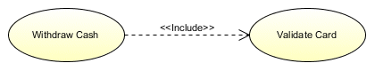
The Withdraw Cash use case includes the Validate Card use case
The included use case will have its own use case description. Note, however, that although the included use case may interact with actors, it will never be directly initiated by an actor. It is only executed when a base use case that includes it is executed. Removing duplicate functionality to a separate use case reduces the amount of documentation required for each of the base use cases that uses the common behaviour, and means that changes to the documentation required for the common behaviour, if required, only need to be made in one place. The use case description for each base use case must indicate the point within its behaviour at which the included use case is executed. In the example below, three use cases (representing three different types of ATM transaction) all include the Validate Card use case.
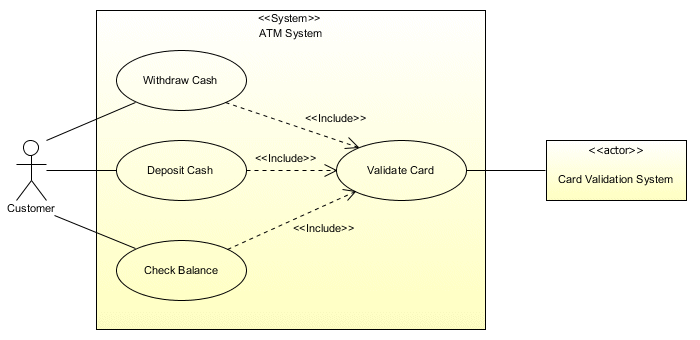
The Validate Card use case is included in three base use cases
Use case descriptions
In order to keep use case diagrams simple, details of the behaviour defined by a use case are documented in a separate document usually referred to as a use case description. Whilst the UML does not specify a format for this document, it is usually (though not necessarily) a simple text document. Every use case should be accompanied by a use case description, whether it is classed as a base use case, an extension, or an included use case. The use case description provides details of the sequence of steps to be carried out in order for the use case to be executed successfully. It specifies the points in this sequence of steps at which any included use cases are executed. It also specifies the extension points at which any applicable extended use cases may be executed, and the conditions that must be true in order for these extended use cases to be applied. The use case description could be expected to include information such as:
- the name of the use case
- a brief description of the use case
- the actor (or actors) responsible for initiating the use case
- the actor (or actors) receiving the results of executing a use case
- pre-conditions (conditions that must be true before a use case can be executed)
- post-conditions (conditions that must be true after a use case is executed successfully) - in other words the criteria for successful outcome (these criteria may well form the basis for black box testing during the software development process)
- the main flow of execution (i.e. the steps that take place if the use case behaves as expected and completes successfully, and the order in which they occur)
- alternate paths through the use case (e.g. the steps that may occur in the event of an exception or error occurring, or the selection of optional behaviour defined in an extended use case)
The steps required for each of the various possible pathways through a use case (sometimes referred to as scenarios) may be written informally, or as a set of numbered statements. Similarly, the conditions that may trigger the error handling or optional behaviour described in an extended use case may be expressed using natural language or a more formal language such as the Object Constraint Language (OCL). Note that while an included use case contains behaviour that is required in order for the base use case to complete successfully, an extended use case usually represents either optional behaviour that may be executed prior to successful completion of the base use case, or as a response to errors or exceptions occurring during the execution of the base use case. In the latter case, the extended use case may allow the base use case to resume at some point, but may equally well cause the base use case to terminate without completing successfully.
Ownership of a use case
Use cases can be owned either by a package or by a classifier (typically, in the case of a classifier, by a system or subsystem - referred to formally by the UML as the subject). We have already seen examples of use cases owned by a system or subsystem, in which the subject is represented by a rectangle which encloses the use case icons, and which displays the name of the system (or subsystem), together with the appropriate stereotype, at the top of the rectangle. Grouping use cases into packages is a valid option if you have a large number of use cases and want to organise them, as illustrated below.
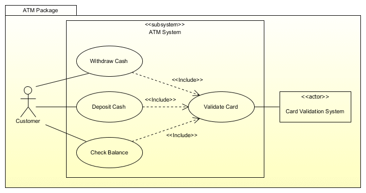
A use case owned by a single package
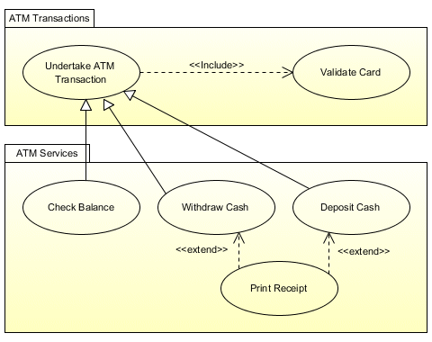
Use cases owned by a different packages
Note that in the second of the examples shown above (which are similar to those given in the UML Superstructure document), the use case Undertake ATM Transaction generalises the use cases Check Balance, Withdraw Cash and Deposit Cash. Although generalisation of use cases is not specifically discussed in the document, the implication is that a specialised use case may inherit the characteristics of a more general (probably abstract) use case. The same principle could be applied to actors, where one actor generalises a number of more specialised actors. A system administrator, for example, has the same characteristics as a user, but also has a number of additional privileges that allow them to carry out administrative tasks. Arguably, specialisations in use cases could be represented by extensions, but the UML Superstructure does not seem to indicate the circumstances under which either of these two possible approaches should be used.