Communication Channels
Overview
A communication channel is a pathway along which information is sent from one place to another. The signal carrying the information may require a guided medium such as a copper cable or an optical fibre, or it may propagate through an unguided medium (generally referred to as free space). Communication systems that use unguided communication channels include satellite networks, mobile networks and wireless LANs. A channel may connect two endpoints directly, or it may be one of several channels that are connected together in some way to form an end-to-end connection.
The earliest forms of telecommunication, going back hundreds, or even thousands of years, include smoke signals and warning beacons consisting of fires lit on the tops of hills. Because such communication requires line-of-sight, the distance over which communication can take place is limited to a few kilometres due to the curvature of the Earth, although that distance increases significantly if the participants occupy elevated positions. Today, navigation lights are used by both ships and aircraft to alert others of their presence. Ships above a certain tonnage, and all passenger ships, are required by law to maintain daylight signalling lamps.
One ancient form of line-of-sight communication still in use today is the lighthouse - an elevated structure housing a powerful lamp, whose purpose is to warn mariners of a coastal hazard, or to provide a navigational point of reference. The use of lighthouses is in decline due to the advent of sophisticated electronic navigation systems.

A lighthouse is an ancient form of communication used to warn of costal hazards
Photograph: Paulius Dragunas
Modern line-of-sight communication channels include point-to-point microwave and laser links. One very familiar example of line of sight communication, albeit somewhat trivial, is the ubiquitous TV remote control that can be found in most homes. When a button is pressed on the remote control, the device generates the corresponding control signal and sends it to the infrared receiver on the television set as a coded sequence of infrared light pulses. The infrared pulses are emitted from the front-facing end of the remote control, which must be pointing - at least approximately - in the direction of the television set.
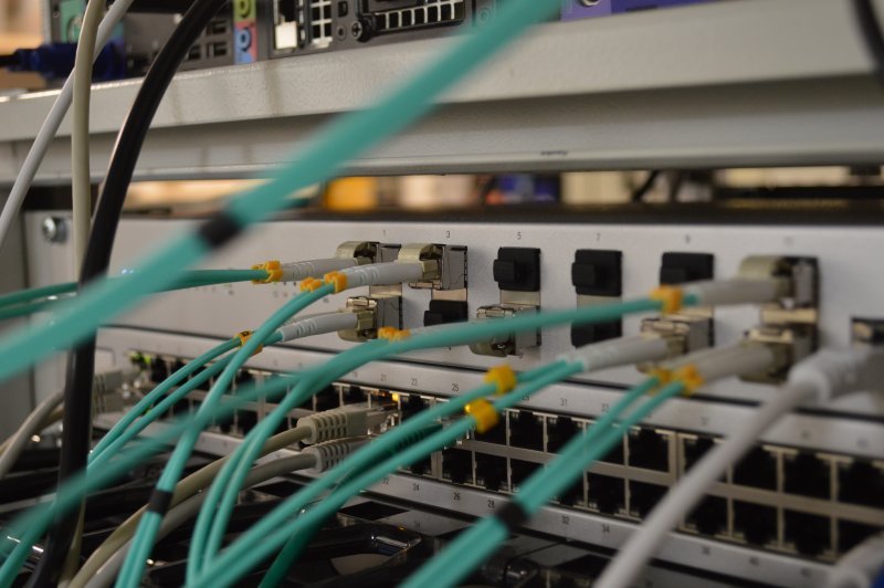
A communications network can employ many different kinds of communication channel. Most local area networks, for example, are implemented using a combination of fixed links and wireless links. High-speed fibre optic cables are typically used to interconnect critical network devices such as routers, switches, hubs, and network servers. Twisted-pair copper cables are used to connect desktop computers to network hubs or switches, and wireless links are used to provide network access to users with mobile computers and hand-held devices as they move from one location to another.
The type of channel chosen for a particular link within the fixed infrastructure of a network will depend on cost, data carrying capacity, and ease of installation and maintenance. The backbone of a network typically consists of fixed links that are required to carry a high volume of network traffic, so it is worth investing in high-speed optical fibre connections. The links between network switches or hubs and individual workstations, on the other hand, usually carry a relatively small amount of data. They are more likely to be implemented using copper twisted-pair cables, which are relatively inexpensive, easy to install and maintain, and have more than enough capacity to meet end-user needs.
For local area networks, the core network infrastructure will probably continue to be implemented using a combination of optical fibre and copper cabling for the foreseeable future, but there has been a phenomenal growth in the use of wireless networking and mobile communications in recent years. Although wireless connections are still generally slower than their fixed network counterparts, the gap is steadily closing.
The same essentially applies to telephony and Internet services. Core connectivity is today almost exclusively achieved using high-capacity optical fibre links, but access networks tend to use a mix of copper and fibre links, and end user connectivity is becoming increasingly wireless thanks to the almost universal availability of affordable mobile devices and rapid advancements in wireless and mobile network technology.
Channel characteristics
Every communication channel falls into one or more categories, depending on its specific characteristics. The list below attempts to outline the main features that may be used to define a particular channel type.
- Guided or unguided - perhaps the most fundamental characteristic of a communication channel is whether the electromagnetic waves that constitute the signal it carries are channelled through some kind of physical waveguide like a copper cable or an optical fibre, or whether they are allowed to propagate freely though "free space".
- Analogue or digital - a communications channel is usually (though not always) designed to carry either digital or analogue data, but not both.
- Bandwidth - in the truest sense of the word, the bandwidth of a channel is the analogue bandwidth - i.e. the difference between the highest and lowest frequencies the channel can support. Note that these may be the highest and lowest frequencies supported by the physical medium that carries the signal or, in the case of a filtered signal, the highest and lowest frequencies allowed to pass through the filter.
- Maximum signalling rate - otherwise known as the baud rate. For the transmission of digital data, this metric indicates The maximum number of signalling symbols that can be transmitted on the given channel per unit time. The maximum signalling rate achievable for a given channel is directly proportional to the channel's analogue bandwidth.
- Maximum bit rate - or gross bit rate. For the transmission of digital data, this metric indicates the maximum number of bits that can be transmitted on the given channel per unit time. The maximum bit rate is closely related to the maximum signalling rate (the exact relationship depends on the number of bits each signal symbol represents).
- Latency and propagation speed - latency is the length of time a signal takes to propagate from the transmitter at one end of a channel to the receiver at the other end. This will ultimately depend on the speed at which the signal propagates through the channel and the distance between the transmitter and the receiver. The propagation speed depends in turn on the physical characteristics of the channel. Electromagnetic waves propagate through a vacuum at the speed of light, and only marginally slower through the Earth's atmosphere. Electromagnetic waves travelling through a copper cable, on the other hand, typically travel at roughly two-thirds the speed of light.
- Transmission direction - a simplex communication channel can carry a signal in one direction only, i.e. from the transmitter to the receiver. A half-duplex channel can carry a signal in both directions, but not at the same time. Each party involved in the exchange of data acts as both a transmitter and a receiver, and a strict protocol must be followed in order to determine who may transmit, when they may transmit, and for how long. A full-duplex channel can carry data in both directions simultaneously, and each participating party act as both a transmitter and as a receiver.
- Transmission impairments - a transmission impairment is any factor the hinders the reliable transmission of data between a transmitter and a receiver on a given channel. All channels suffer from transmission impairments of one kind or another, the precise nature of which depends on the type of transmission medium used to carry the signal and the frequencies used to transmit the data. There are essentially three basic types of transmission impairment - attenuation, noise, and distortion.
- Attenuation is loss of signal power caused by the physical characteristics of the transmission medium. In optical fibres, for example, some of the light passing through the fibre is absorbed by molecules in the glass and converted to heat energy. Some light will be deflected from its path due to collisions with individual atoms, and will escape from the fibre core.
- Noise is the presence of electromagnetic interference that has a negative impact on the signal carrying the information. Examples include the thermal noise caused by the vibration of electrons in electrical conductors, the random signals generated by external sources such as heavy machinery, vehicle ignition systems, and microwave ovens, and the crosstalk that can occur between parallel communication circuits.
- Distortion is an unwanted change in the waveform of a signal (which usually entails changes to the amplitude, phase or frequency of the signal) due to imperfections in the transmission system. For example, distortion can be caused by an amplification (or attenuation) process that is not applied equally across the signal's frequency range. A mismatched impedance anywhere in the system can cause some of the signal to be reflected back towards its source, creating interference.
- Unicast, multicast or broadcast - these characteristics usually refer to a signal that is sent by a single transmitting station on a network to all of the other stations attached to the network, but that is not necessarily intended to be read by all of them. The signal may be intended for a single receiver (unicast), some subset of the receivers on the network (multicast), or to every receiver on the network (broadcast). In the case of unicast or multicast transmissions, valid receiving stations are identified by a network address of some kind. Note that a unicast channel is not the same thing as a point-to-point link, which is usually a physical connection between a single transmitter and a single receiver, although in the case of a point-to-point laser or microwave link, it takes the form of a directed beam.
Guided media
The term guided media essentially refers to a physical connection between two devices - usually a cable of some kind. Some cables carry electrical signals using copper wire conductors, others carry pulses of light using optical fibres made from high-purity glass or plastic. The following types of guided media are commonly used in telecommunication systems:
- Unshielded twisted-pair (UTP) cable
- Shielded twisted-pair (STP) cable
- Coaxial cable
- Single-mode optical fibre cable
- Multi-mode optical fibre cable
- Plastic optical fibre (POF) cable
In the first three types of cable listed above, the transmission medium consists of two or more copper conductors, and the signals that propagate along these copper conductors are electrical in nature. The last three items in the list are the most commonly-used fibre optic cable types. The signals that propagate through optical fibres take the form of light pulses. Even though copper and fibre optic cables carry very different types of signal, all of the signals consist of electromagnetic waves.
The cable itself acts as a waveguide. In general terms, a waveguide is a physical structure that forces electromagnetic waves to travel in a single direction, as opposed to being radiated outwards from their point of origin in all directions. This allows the wave to propagate over relatively long distances with minimal loss of energy. In a twisted-pair Ethernet cable, for example, each wire pair provides a waveguide for an Ethernet signal. In a fibre optic cable, each fibre strand acts as a waveguide for a stream of light pulses.
The main difference between copper cables and fibre optic cables is that the copper conductors in a twisted-pair or coaxial cable carry an alternating electrical current, which means that they will radiate energy in the form of electromagnetic waves. The construction of coaxial and twisted-pair copper cables is designed to minimise this effect, but some energy will still be lost as the signal propagates along the cable, limiting the distance over which signals can be carried before they need to be regenerated.
An optical fibre does not radiate electromagnetic energy, and although some energy is lost due to the absorption and scattering of light within the fibre itself, the energy losses are far lower than for copper cables. As a consequence, a fibre optic link can carry signals over a much greater distance than a twisted-pair or coaxial copper cable.
Fibre optic links can carry signals over great distances
Fibre optic cables are used almost exclusively in the core networks that make up the Internet and the telephone system because of their high data rates, low power loss, and immunity to electrical noise. The downside of fibre optic cables is that they are expensive and relatively difficult to install and maintain by comparison with copper cable. The connection and termination points are also sensitive to mechanical disturbances. In computer networks, they are typically used for the fixed links that connect critical devices such as routers, network switches and hubs. Twisted-pair Ethernet cables are used for most other fixed network connections because they are cheap, robust, and easy to install and maintain.
Coaxial cables are no longer widely used in computer networks, having been largely replaced by twisted-pair Ethernet cables or fibre optic links, but they are still used in cable TV systems to deliver television programmes and broadband Internet services to consumers. They are also used to carry signals from a television antenna or satellite dish to a television set or set-top box.
Wired channels
Wired channels physically connect a transmitter to a receiver using (usually) copper cables. The most commonly used types of copper cabling are twisted-pair cables and coaxial cables. Twisted-pair cables have been used in the Public Switched Telephone Network (PSTN) since the early 1890s, and are still widely used today in the subscriber loop of the PSTN. They are also used in both local area networks (LANs) and home computer networks to carry data between workstations and network devices such as hubs, switches and routers. They have also been used to connect core network devices, although in this sphere they have largely been replaced by fibre optic cables.
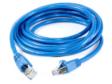
Twisted-pair Ethernet cables are used in LANs and home networks
A twisted-pair cable, as the name suggests, contains one or more pairs of thin (typically 0.52 mm or 0.57 mm in diameter), insulated copper wires. Telephone cables can contain anything from two twisted-pairs up to several hundred, depending on where in the telephone network they are used. A twisted-pair Ethernet cable of the type typically used in a computer network contains just four twisted-pairs, each of which provides a balanced transmission circuit. This means that each wire pair constitutes a transmission line consisting of two conductors of the same type, each having equal impedances along their lengths and equal impedances to ground and other circuits.
A single balanced wire pair in isolation could be left as a parallel arrangement It will have a reasonable amount of immunity to relatively distant sources of electromagnetic interference, because the interference from these sources will induce equal currents in both the forward and return path of the circuit. Because the currents induced in each of the two wires are equal, a common-mode signal is created by the noise voltage induced on each conductor which can be detected by the receiver and subtracted from the incoming signal to leave just the transmitted signal.
When two or more wire pairs are bundled together in the same cable, the signals they carry will interfere with one another if the wires are parallel because one wire in each pair tends to be closer than the other to the electromagnetic interference generated by a neighbouring pair, resulting in a greater current being generated in that wire. Twisting the wires in each pair together means that both wires in each pair will be equally exposed to the interference created by an adjacent wire pair, and the receiver will detect and eliminate the resulting common mode signal.
The wires in each pair are twisted together to reduce "crosstalk"
Each pair in a twisted-pair Ethernet cable has a slightly different twist ratio to ensure that two wires from two different pairs do not repeatedly lie next to each other, undoing the beneficial effects of the twisting. The precise ratio of twisting in each pair is tightly controlled by cable manufacturers, and forms part of the technical specification for a particular cable type.
The term cross-talk is often used to describe interference between wire pairs in a cable, because in some older types of telephone cable the wire pairs were not always properly balanced with respect to one another. This could sometimes lead to a situation where voice signals from one telephone line created an "echo" on a neighbouring telephone line. If two telephone calls were taking place simultaneously over adjacent wire pairs, one pair of subscribers could hear the conversation taking place between the other pair of subscribers, and vice versa.
Coaxial cables have also been used extensively for cabling local area networks in the past, but are rarely found in LANS or home computer networks today. They are still widely used in industrial control networks, because their shielding makes them resistant to sources of electrical interference such as motors and heavy machinery. They are also ubiquitous in the home, where they are used to carry television signals from a satellite dish, television antenna, or cable TV outlet to a television or set-top box.
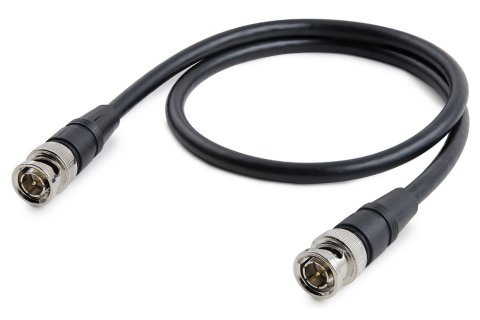
A coaxial cable consists of a single central conducting wire inside a flexible cylindrical sheath made from a dielectric (non-conducting) material. The dielectric sheath is surrounded by an outer conducting shell, typically constructed using tinned copper or aluminium foil, or braided copper wire. The result is an electrically shielded transmission path in which current flow is restricted to the adjacent surfaces of the inner and outer conductors, and the associated electromagnetic field propagates within the dielectric insulator.

A coaxial cable has a central conductor surrounded by a dielectric sheath and an outer conducting shield
Because of the coaxial cable's unique construction, very little energy is lost in the form of electromagnetic radiation, and the signal is shielded from external interference by the outer conductor. Unlike twisted pair cables, coaxial cable does not employ a balanced pair. Instead, the outer (return) conductor is connected to ground, and the signal-carrying voltage is applied to the inner conductor. The dielectric sheath is constructed to precise specifications in order to maintain the spacing between the central and outer conductors.
Coaxial cables can carry significantly higher-frequency signals than twisted-pair cables, and have a much greater bandwidth. Like twisted-pair cables, coaxial cables suffer from signal attenuation, but they can carry signals over greater distances before a repeater is required. In the first Ethernet networks, the backbone of the network itself was typically constructed using 10BASE5 coaxial cable, which could be used for spans of up to 500 metres. The cables were thick and fairly rigid, earning them the name "ThickNet" and making them relatively difficult to install and terminate.
Thinner, 10BASE2 coaxial cables - known as "ThinNet" or sometimes "CheaperNet" - were used to connect network computers to the network backbone. These cables could reliably carry data for distances of up to 200 metres, as opposed to a maximum distance of 100 metres for a twisted-pair Ethernet cable. They were more flexible and easier to work with than 10BASE5, but still both more expensive and more difficult to install and maintain than the twisted pair Ethernet cables that eventually replaced them.
Optical fibre channels
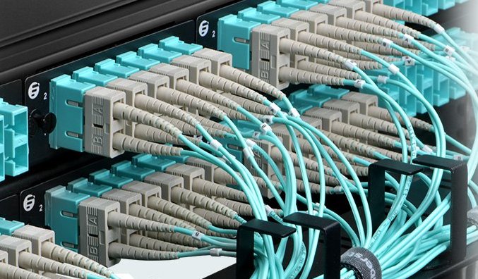
Fibre optic cables are increasingly used in local area networks to carry data over fixed links between major network devices, although due to cost considerations and the sensitivity of fibre optic connections to mechanical disturbance, it is unlikely that they will replace twisted-pair Ethernet cables in providing hard-wired connections between workstations and network switches or hubs. Optical fibres are also used almost exclusively in the core networks of the Internet and the telephone system due to their immunity to electrical interference, high data rates, and the fact that they can carry data reliably over very long distances (typically 100 kilometres) before signals need to be regenerated using an optical repeater.
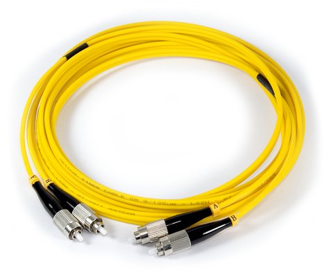
Fibre-optic cables are used extensively in core telecommunications networks and LANs
An optical fibre carries data from a transmitter to a receiver in the form of a modulated beam of monochromatic (single-colour) light. The core of an optical fibre is a very fine strand of high-purity glass or plastic, typically 8 to 50 microns in diameter (comparable with the thickness of a human hair), that acts as an optical waveguide. Surrounding the core is a layer of transparent cladding, also made from glass or plastic, and having an outer diameter of approximately 125 microns.
The cladding, although also transparent, has a lower refractive index than the core. This means that, as long as any light travelling through the core is incident on the cladding at less than the corresponding critical angle, it will be reflected back into the core - a phenomenon known as total internal reflection. Light is thus unable to escape from the core, and will be transmitted from one end of the fibre to the other with minimal loss of signal. The cladding is in turn surrounded by a protective layer of an opaque material, usually some kind of plastic, known as the primary buffer. Several fibres can be bundled together around a central strength member inside a common sheath to form a fibre-optic cable.
Cross-section and longitudinal section of a typical optical fibre
The properties of a particular optical fibre depend largely on two factors - the diameter of the fibre core and the degree to which the refractive index varies across the diameter of the core. Although there are numerous permutations for these two factors, we'll confine ourselves to the basics. We'll deal with the question of refractive index first. There are two major variants: stepped-index fibre, in which the refractive index of the core is constant across its diameter, and graded-index fibre, in which the refractive index tapers smoothly between the centre of the core and its interface with the cladding.
In a stepped-index fibre, light entering the fibre will follow different paths through the fibre, depending on the angle at which it enters the fibre from the light source at the transmitter. Light entering the fibre at a relatively shallow angle will follow a shorter path through the fibre than light entering at a steeper angle, and will thus arrive at the receiver earlier - a phenomenon known as multimode dispersion. This is not usually a significant problem over short distances, but over longer distances it may cause the signal to spread out (a phenomenon known as pulse-spreading) to such an extent that, by the time it reaches the receiver, individual signal symbols overlap one another (this is known as intersymbol interference).
The effects of pulse spreading in a stepped-index fibre can be mitigated by reducing the data rate to ensure that consecutive symbols do not overlap, or restricting the distance over which such a fibre is used, although this places obvious constraints on both the data rates achievable and the type of application for which the fibre can be used. Alternatively, a graded-index fibre can be used, in which the variations in the refractive index across the diameter of the core are designed to reduce multimode dispersion by forcing light to follow a sinusoidal path through the fibre, regardless of the angle of entry.
The optical fibres described above are known as multimode fibres because the light may follow many different paths through the core. By reducing the diameter of the core to between 8 and 10 microns, it becomes possible to limit the light waves passing through the core to a single transverse mode in which the light travels parallel with the length of the fibre. This kind of optical fibre is known as a single mode fibre, and is commonly used for long-haul data links because it virtually eliminates multimode dispersion.
Light transmission in a single mode fibre
The main limitations on the distance over which an optical fibre can carry data (other than those associated with multimode fibres) are the absorption of light by impurities in the core, and the scattering of light due to random variations in the density of the core material. These will eventually result in signal attenuation over long distances, necessitating the regeneration and retransmission of the signal using an optical repeater.
The extremely high frequencies supported by optical fibres means that very high data rates can be achieved. In fact, several experimental networks have already achieved data rates in excess of 40 terabits per second (that's more than 40 trillion bits per second!) over a single optical fibre using a laser transmitter.
A single optical fibre link consists of an electro-optical transmitter that converts an electronic digital signal into a modulated beam of light, an opto-electrical receiver that demodulates the modulated light beam and turns it back into an electronic digital signal, and of course the optical fibre itself, which provides the transmission path. This means that, for two-way communication, two optical fibre links are required.
The type of transmitter used will depend on the application. For standard data rates, or over relatively short spans for which multimode dispersion is not a particular concern, a low-cost light-emitting diode (LED) can be used. For longer spans and/or higher data rates, a semiconductor laser is used. The semiconductor laser is more expensive and has a shorter lifetime than the LED, but its light output can be coupled to the optical fibre more efficiently, and it has the faster rise time necessary to achieve very high signalling rates.
Fibre optic cables are significantly more expensive than either twisted-pair or coaxial cables, and are also more difficult to install and maintain. Optical transmitters and receivers must be precisely aligned with the optical fibre, which is no mean feat considering the small diameter of the fibre core, and splicing two fibres together in the field requires highly specialised equipment and skills. Nevertheless, optical fibre has many advantages.
Because signals are transmitted as pulses of light, they are not susceptible to disruption from electrical interference. Indeed, a fibre optic cable can be run alongside high-voltage power cables without suffering any adverse effects. Optical fibres are also more secure than copper cables because they do not radiate electromagnetic energy, and are thus far less susceptible to eavesdropping. They can also be used over longer distances than copper cables thanks to low attenuation. Fibres optic cables are now used for almost all long distance high-capacity data links, telephone trunk lines, and network backbones.
Unguided media
The term unguided media refers to any medium through which electromagnetic waves can travel without having to rely on a physical connection. The medium in question could be the vacuum of space, the Earth's atmosphere, a body of water, or even a solid object, depending on the type of electromagnetic wave involved and the material(s) from which the object is made. The way in which electromagnetic waves propagate through an unguided medium depend on two co-dependent variables - frequency and wavelength. They also depend, of course, on the properties of the medium itself.
Signals propagate through an unguided medium from a transmitter to a receiver. In most cases - broadcast radio for example - an omnidirectional antenna radiates a signal in every direction, and the signal is received by multiple receiving antennae. In some cases, such as a point-to-point microwave link, a directional antenna is used to focus the signal into a narrow beam directed at the receiving antenna. The term "unguided" can still be (loosely) applied in this case, because there is no physical waveguide. Because signals can propagate over a significant distance without requiring a physical medium, unguided transmission can be used for applications where the installation of cables would be impractical or too costly.
The uses to which various parts of the electromagnetic spectrum are put is dependent on frequency and wavelength. In theory, the entire electromagnetic spectrum could be used for telecommunications, but the range of frequencies that can be used for commercial applications is limited. Visible light, which occupies the frequency band 400 - 789 terahertz (corresponding to wavelengths in the range 750 - 380 nanometres), has been used to communicate in one way or another throughout the history of telecommunications. Frequencies above this range include extreme ultraviolet light, x-rays, and gamma rays, all of which are forms of ionising radiation, making them harmful to humans and thus unsuitable for use in commercial telecommunication systems. The harmful effects of such radiation increase with frequency.
There are three primary modes of propagation in an unguided medium:
- Atmospheric propagation - electromagnetic waves travel through the atmosphere at speeds approaching that of light along a single path between a transmitter and a receiver. Depending on wavelength, the signal can travel in a straight line or may bend around obstacles such as buildings. or even larger obstacles like hills, thanks to a phenomenon known as ray diffraction (a full discussion of this topic is beyond the scope of this article). This means that a direct line of sight between transmitter and receiver is not always required.
- Groundwaves - at relatively low frequencies, electromagnetic waves will travel along the surface of the Earth as if it were acting as a waveguide. The distance over which a signal can travel as a groundwave will depend on wavelength and the electrical conductivity of the surface over which it travels. Signals at longer wavelengths tend to travel further than those at shorter wavelengths. Signals will also travel further over the ocean than over land, because the surface of the ocean has a much higher conductivity.
- Reflection - electromagnetic waves can be totally or partially reflected when they encounter an interface between the medium through which they are travelling and some other medium. A mirror reflects virtually all of the light incident upon it, which is why you see your image when you stand in front of it. You see objects in the world around you because they reflect light. Radio waves and microwaves are also reflected when they encounter an interface with suitable properties. Most radio waves (by which we refer to frequencies between 3 hertz and 300 megahertz) can propagate through the atmosphere along a zig-zag path, alternately being reflected by the ionosphere and the Earth's surface (this is sometimes called skywave propagation).
The three primary modes of unguided signal propagation
The distances over which we can communicate using an unguided medium will very much depend on the properties of the medium itself, and the kind of signal we are transmitting. We can use radio frequencies to communicate over very long distances because signals at these frequencies do not require a line-of-sight between transmitter and receiver. They can use any of the propagation methods described above.
Microwave signals, because of their much higher frequencies, are not reflected by the ionosphere, and thus tend to be constrained to line-of-sight for long-distance applications, although like radio waves, they can pass relatively easily through non-conductive materials and may also be reflected by buildings, which is why you don't need a direct line-of-sight with a cellular base station to use your cell phone.
One thing to be aware of when it comes to signal propagation through an unguided media is that, unlike with a copper cable or optical fibre, the conditions that a signal will encounter during transmission are to some extent unpredictable. Atmospheric conditions such as heavy rainfall can significantly attenuate radio and microwave signals, and short-to-medium range line-of-sight communications systems such as laser and microwave links can be severely disrupted by fog.
Bear in mind also that the signal transmitted by an omnidirectional antenna radiates outwards in every direction simultaneously. The strength of the signal received will thus depend on the distance travelled by the signal before it reaches the receiving antenna. Even ignoring the effects of signal attenuation caused by external factors such as atmospheric conditions, signal strength will fall off significantly as the distance from the transmitter increases, in accordance with the inverse square law:
| P r = P t × | 1 |
| r 2 |
where P t is the power of the transmitted signal, P r is the power of the received signal, and r is the distance between the transmitter and the receiver. Signal strength will also fall off with distance for a focused beam, but not to the same extent. The exact amount by which the power of a directional signal falls off will be determined by factors such as antenna design and how narrowly the beam can be focused.
Low frequency radio
At the bottom end of the electromagnetic spectrum, we have extremely low frequency (ELF) radio waves, with frequencies ranging from 3 to 30 hertz, corresponding to wavelengths of 100,000 to 10,000 kilometres. Because the antennae required to radiate such waves must be tens of kilometres in length, this portion of the EM spectrum has no practical commercial application. A few countries - notably the USA, Russia and China - have in the past used these frequencies for military applications. ELF waves can penetrate seawater, and can thus be used to communicate with submerged submarines.
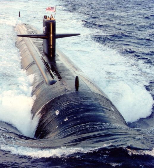
Frequencies in the ELF band have in the past been used to communicate with submarines
Photograph: US Navy - USS Los Angeles
The band of frequencies above ELF is called the super low frequency (SLF) band, and consists of radio waves with frequencies ranging from 30 to 300 hertz, corresponding to wavelengths of 10,000 to 1,000 kilometres (note that some sources consider this frequency band to be part of the ELF band). Like ELF, SLF has no practical commercial applications, but has in the past been used to communicate with submarines. The Indian Navy currently uses SLF frequencies to communicate with its ballistic missile and attack submarines.
Above the SLF band, we have the ultra low frequency (ULF) band, which occupies the frequency range 300 hertz to 3 kilohertz, with wavelengths from 1,000 to 100 kilometres. Radio waves in this band can penetrate the earth, and are used for communication in mines. Communication through the ground using conduction fields is called Earth Mode communications. Like the ELF and SLF bands, ULF has been used for military communications. It has also been used for communications over relatively short distances by amateur radio enthusiasts.
The next band in the electromagnetic spectrum is the very low frequency (VLF) band, which spans the frequency range 3 to 30 kilohertz, corresponding to a wavelength range of 100 to 10 kilometres. Like the frequency bands below it, it is not practical for commercial applications for a number of reasons, including low bandwidth and the difficulty of constructing suitable antennae. It is however used for secure military communications, notably to communicate with submarines due to the fact that it can penetrate seawater for a depth of up to 40 metres.
VLF waves can propagate as ground waves for several hundred miles, following the curvature of the Earth, but can also be used to communicate - albeit at low data rates - over much longer distances (up to 20,000 kilometres) through the Earth's atmosphere, essentially travelling in a zigzag path around the Earth, alternately being reflected by the ionosphere and the Earth's surface. The VLF band has been used in the past to transmit signals that can be used by ships and aircraft to determine their position, and is also used by some radio amateurs.
Other radio frequencies
Radio frequencies are generally considered to range from 3 hertz up to 300 gigahertz. However, as we have seen, the ELF, SLF, ULF and VLF bands are not really practical for mainstream telecommunications applications. We should also consider that usable frequencies of 300 megahertz and above are usually classed as microwave frequencies, although definitions vary. The distinction between what is classed as radio communication and what is classed as microwave communication is often blurred.
The band of radio frequencies immediately above the VLF band is called the low frequency (LF) or longwave band, and ranges from 30 kilohertz to 300 kilohertz. The corresponding wavelengths range from 10 kilometres down to 1 kilometre. Like VLF signals, LF signals can travel as ground waves over long distances (up to 2,000 kilometres) with relatively low attenuation, making them suitable for long-distance communication. They can also propagate through the atmosphere for distances or up to 300 kilometres or more because the waves are refracted by the ionosphere, although this is not the primary mode of propagation.
Groundwaves are vertically polarised (this means that the electric field is vertical, while the magnetic field is horizontal). The transmitting antenna is thus usually a vertical monopole antenna (the subject of monopole versus dipole antennae will be dealt with elsewhere). Depending on the application, antennae can be anywhere from 10 metres to 400 metres high. AM radio stations that broadcast on the longwave band typically use mast antennae with heights of around 150 metres.
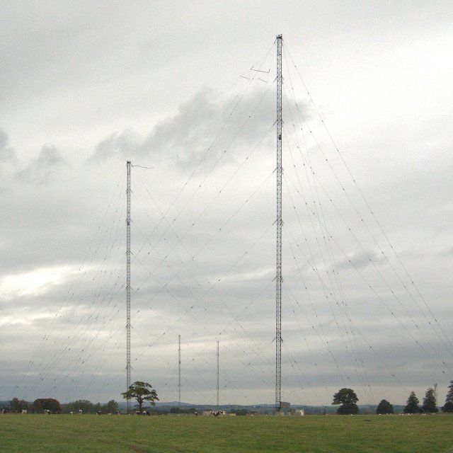
The Droitwich transmitting station - home of the BBC's most powerful long-wave transmitter
Photograph: Bob Nienhuis
Longwave commercial radio broadcasting is mostly confined to Europe and parts of North Africa and Asia. Elsewhere, the low frequency band is used to broadcast navigational information and time signals. Under international agreements, a narrow band of frequencies (135.7-137.8 kHz) has been set aside for amateur radio use. Communication typically consists of an exchange of Morse code messages. Named after its inventor Samuel Morse (1791-1872), the code consists of sequences of dots and dashes that represent various alphanumeric characters and other symbols.
Above the LF band lies the medium frequency (MF) band which occupies the radio frequency band 300 kilohertz to 3 megahertz, corresponding to wavelengths from 1000 metres to 100 metres. The medium frequency band includes the frequencies used for medium wave commercial radio broadcasts. MF signals can travel over distances of several hundred kilometres as groundwaves, and for even greater distances if the signal is refracted by the ionosphere, although groundwaves are the primary method of propagation.
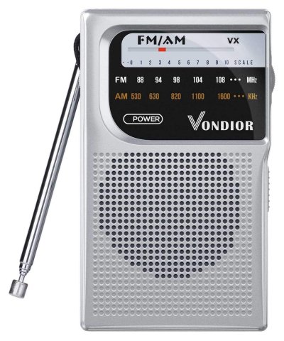
The MF band includes the frequencies used for medium wave commercial radio
An interesting problem arises with commercial AM radio medium wave broadcasts. Stations sufficiently far apart can generally use the same frequencies to broadcast because the transmitted signals have a limited range if they propagate as groundwaves. Signals that propagate via the ionosphere can travel further, but are absorbed during the day by the lower layers of the ionosphere and thus do not interfere with the signals transmitted by other stations. The story is different at night, when ionisation of these low-lying layers in the ionosphere virtually ceases and they can no longer absorb the MF signals. To prevent stations interfering with each other, signal power output must be reduced at night, although this can also impact on reception.
As with the LF band, the transmitting antenna is usually a vertical monopole antenna, and (depending on application) can be anywhere from 25 metres to 250 metres high. AM radio stations that broadcast on the medium wave band typically use mast antennae with heights of between 47 metres and 141 metres depending on frequency, although due to cost considerations other types of antenna requiring shorter masts are sometimes used.
Besides commercial AM radio broadcasts, the MF band is used for applications such as navigational radio beacons, ship-to-shore communications, and air traffic control. It also includes the so-called 160 metre band or top band - the range of frequencies between 1800 and 2000 kilohertz set aside for amateur radio - which can carry Morse code, digital data or voice signals. This is not the only amateur band within the MF band, but it is by far the oldest. It was first allocated for worldwide use by the International Radiotelegraph Conference of 1927.
Above the medium frequency band lies the high frequency (HF) band. This band covers the frequencies from 3 megahertz to 30 megahertz, corresponding to wavelengths of 100 metres down to 10 metres, and is part of the shortwave band of radio frequencies. The primary mode of propagation for HF signals is as reflected waves (often referred to as skywaves). Radio waves are directed at the ionosphere at an angle and are refracted back to Earth. This means that communication is possible over long distances, and in mountainous terrain where direct atmospheric propagation cannot be used.
Use of the HF band for communication is constrained by a number of environmental factors, including the time of day, the time of year, and solar activity. These factors combine to determine the minimum and maximum usable frequencies at any given time. The time of day is an important factor because the ionisation in the ionosphere is generated by solar radiation. During the day, the lower layer of the ionosphere is highly ionised and tends to absorb radio waves at the lower end of the HF band, while those at higher frequencies are reflected back towards the Earth's surface.
At night, the position is reversed. The lower layer of the ionosphere essentially disappears, allowing the low frequency waves to reach the upper layers of the ionosphere. These layers are at a much higher altitude and thus have a lower gas density. They are still ionised, but now act to reflect the lower frequencies back towards the Earth instead of absorbing them. The higher frequencies, on the other hand, now tend to pass through the ionised layers rather than being reflected.
The seasonal variations are explained by the fact that there is more solar radiation incident on the ionosphere during the summer than during the winter. Solar flares can also temporarily disrupt radio communications, but a more significant factor is sunspot activity, which can increase the overall levels of solar radiation, resulting in increased levels of ionisation in the ionosphere.

The antennae used for high frequency transmission are typically horizontal dipole antennae, which emit horizontally polarised waves (the electric field is horizontal, while the magnetic field is vertical). This effectively means that half of the transmitted signal power is directed towards the sky, while the other half is directed towards the ground where it is reflected back towards the sky. The reason for this is that, for the higher frequencies in the HF band at least, the ground has a tendency to absorb vertically polarised waves but reflect horizontally polarised waves.
Because the HF band makes communications possible over very long distances, it has been used for a number of applications, including international and regional shortwave broadcasting, military communication, aviation communication, and both ship-to-shore and ship-to-ship communication. It is also very popular with amateur radio enthusiasts because of the potential for contacting operators on the other side of the world, when the conditions are right, and is also used for citizens' band (CB) radio.
The use of the HF band for aviation, maritime and military communications has declined over the years as more reliable means of long-distance communication (notably satellite links) have become available. Nevertheless, HF systems are often maintained for backup purposes, and the HF band is still very popular with amateur radio operators. Frequencies at the upper end of the HF band are currently used for CB radio, radio-controlled devices such as model aircraft, and for radio pagers.

Frequencies at the upper end of the HF band are used for radio-controlled devices
Photograph: Tyler Casey
The highest band of radio frequencies is the very high frequency (VHF) band, which ranges from 30 to 300 megahertz, corresponding to wavelengths of 10 metres down to 1 metre. VHF signals propagate through the atmosphere mainly by line of sight, although they can also be reflected by the ground. Signals at the lower end of the VHF band may be reflected by the ionosphere, but at higher frequencies they will pass through it and escape into space. VHF signals do not propagate as groundwaves, and are therefore blocked by hills and mountains, but they can be weakly diffracted by the atmosphere, allowing them to be picked up by a receiving antenna at some distance beyond the visible horizon.
Although largely constrained to line-of-sight propagation, VHF signals can penetrate solid objects such as the walls of buildings, and can thus be received by an indoor antenna. They also have the advantage that they are far less susceptible to attenuation caused by spurious radio signals and radio frequency interference from electrical equipment than signals at lower frequencies.
The relatively short wavelengths involved also mean that the antenna used to transmit VHF signals can be made small enough to be mounted on vehicles and portable devices, making the VHF band suitable for applications like two-way mobile radio systems (e.g. "walkie-talkie" radio sets). The antennae for such devices are usually either telescopic or whip antennae like those often seen mounted on cars, or "rubber ducky" antennae.
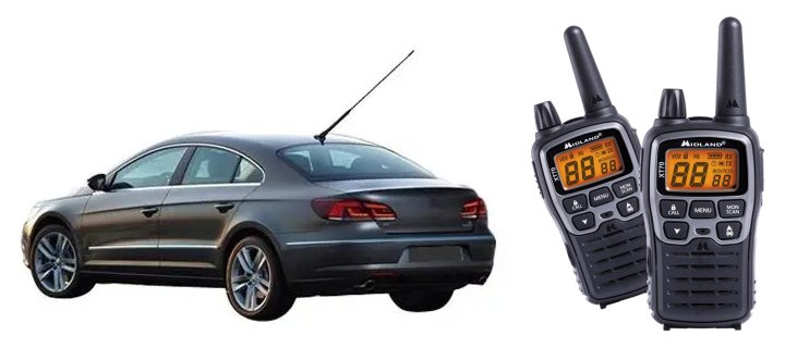
A whip aerial mounted on a car and a pair of two-way radios with "rubber-ducky" aerials
The rubber ducky antenna is a monopole antenna that works in similar fashion to a whip antenna. It consists of a wire coil in the shape of a helix, sealed inside a rubber or plastic jacket. Although not as efficient as a whip antenna, its compact form makes it both safer to use and more convenient for hand-held devices.
Terrestrial television and FM radio broadcasting stations use vertically-oriented, high-gain omnidirectional antennae consisting of collinear arrays of dipole antennae (i.e. arrays of dipole antennae located along a common axis). These antennae arrays radiate vertically or horizontally polarised radio waves in all horizontal directions, and are designed to maximise the power radiated horizontally while minimising the power radiated vertically (i.e. upwards into the sky or downwards into the earth).
The VHF band is used for a number of applications, including digital audio broadcasting (DAB), FM radio broadcasting, television broadcasting, amateur radio, and maritime communications. The lower end of the VHF band overlaps the shortwave radio band. In recent years, partly due to the development of digital terrestrial television (DTT) and partly due to a significant increase in the demand for bandwidth as the number of channels has grown, there has been a steady migration of terrestrial television broadcasting from the VHF band to the ultra high frequency (UHF) band, which lies at the lower end of the microwave spectrum.
Terrestrial microwave
At the lower end of the microwave range we have the ultra high frequency (UHF) band, which includes the frequencies from 300 megahertz up to 3 gigahertz, corresponding to wavelengths of 1 metre down to 10 centimetres. Signal propagation is largely limited to line-of-sight, although the signals can penetrate building walls sufficiently well to allow indoor reception. Because UHF wavelengths are relatively short, both transmitting and receiving antennae, in the form of small dipole or monopole antennae, can be incorporated into hand-held devices such as cell phones, cordless phones, and mobile computing devices.
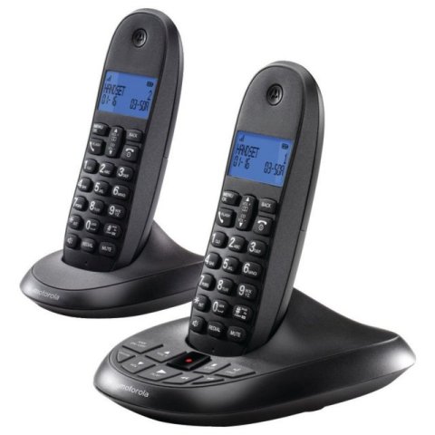
In the UK DECT phones works at frequencies of between 1.88 and 1.9 gigahertz
The UHF band is used for applications such as terrestrial television broadcasting and cellular telephone communication. It is also used in wireless networks, for communication between cordless phones and their base units, and for communication between Bluetooth-enabled devices. UHF frequencies have been used for both analogue and digital terrestrial television broadcasts in the past, although virtually all analogue TV broadcasting has now been phased out in favour of digital transmission.
In the UK, the UHF frequencies allocated for analogue television broadcasting ranged from 470 up to 850 megahertz. However, because a digital television channel occupies significantly less bandwidth than its analogue counterpart, frequencies above 800 megahertz have been reallocated to 4g mobile services, and those between 700 and 800 megahertz are currently being cleared for reallocation to 5g services.
In the middle of the microwave rage lies the super high frequency (SHF) band, which comprises the frequencies 3 to 30 gigahertz, corresponding to wavelengths of from 10 centimetres down to 1 centimetre. Because of their short wavelengths, microwave signals in this band can be focused into a narrow beam using a conveniently sized directional antenna, which can then be pointed directly at a receiving antenna. Microwave antennae are usually mounted on towers or on tall buildings in order to maximise the distance over which they can transmit. The distances involved can range from a few metres up to several tens of kilometres.
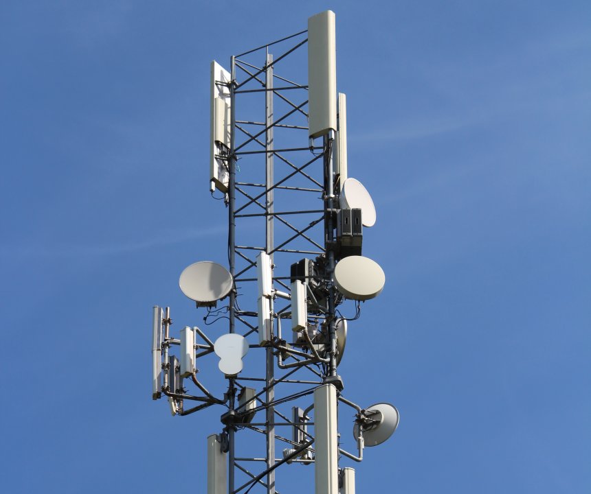
Directional antenna mounted on a microwave tower
Photograph: Chris Wells
The ability to restrict the transmitted signal to a relatively narrow beam means that two or more microwave links can employ the same frequencies without interfering with each other, and the relatively high frequencies involved allow high data rates to be achieved. Point-to-point microwave links can be used to provide telecommunication services to remote areas where the installation of cabled infrastructure would prove too costly or impractical.
SHF frequencies are used extensively in cellular networks to provide the links between the wireless base stations at the edge of the cellular network and the base station controllers connected to the core network. SHF microwave frequencies of between 5 and 6 gigahertz (usually referred to simply as the 5 gigahertz band) are also used in wireless LANs (WLANs) for the wireless links between mobile user devices and wireless access points.
Because microwave signals in the SHF band are limited to line-of-sight transmission, point-to-point microwave radio links have a maximum range of approximately 50 to 65 kilometres, depending on the terrain over which the signal must travel and the height at which the transmitting and receiving antennae are mounted above the ground. For links that must span greater distances (i.e. beyond the horizon), intermediate microwave relay stations are required.
Microwave signals are attenuated by absorption and scattering caused by moisture in the atmosphere - an effect that tends to increase with frequency, and which can cause severe signal attenuation during periods of heavy precipitation, particularly at frequencies of 10 gigahertz and above. Telecommunications system designers must take these factors into account when planning microwave links.
The band of microwave frequencies above the SHF band is called the extremely high frequency (EHF) band, which includes the range of frequencies from 30 to 300 gigahertz, corresponding to wavelengths of from 1 centimetre down to 1millimetre. Microwave signals in this band are subject to a high degree of attenuation due to absorption by the gases in the atmosphere, and are thus only suitable for short range communications. This attenuation increases with frequency such that, at the top end of the EHF band, signals effectively disappear after a few metres.
There are some advantages to using frequencies in the EHF band. The high frequencies involved make very high data transfer rates possible, whilst at the same time allowing the use of very small transmitting and receiving antennae. The relatively limited range also means that the same frequencies can be re-used more often in cellular networks, which translates to being able to provide services to far more users in a given area. The 5G networks currently in development will use two sets of frequency bands. Frequency range 1 (FR1) goes from 450 MHz to 6 GHz, while Frequency range 2 (FR2) goes from 24.25 GHz to 52.6 GHz, offering download rates (in theory, at least) of up to 20 Gbps.
Satellite microwave
In May 1945, physicist and science-fiction author Arthur C. Clarke (1917-2008) completed a paper entitled "The Space-Station: Its Radio Applications" that proposed the use of artificial satellites to implement a global communications system, suggesting that they could be used to broadcast television signals. He further suggested that if a satellite's orbital plane coincided with that of the Earth's equator, and if the satellite was at the correct distance from Earth, then its orbital angular velocity would match the Earth's angular velocity of rotation, and it would maintain its position above a fixed geographical location on the equator.
Today, an orbit of the kind described by Clarke is known as a geostationary orbit, for obvious reasons. In Clarke's vision, three satellites in geostationary orbit, equidistant from one another, would be able to communicate with any point on the Earth's surface (with the possible exception of the extreme polar regions) and with each other. Twenty years later, his vision became a reality when the newly formed intergovernmental consortium Intelsat launched the aptly-named "Early Bird" (Intelsat 1) - the World's first commercial communications satellite - into a geosynchronous orbit.
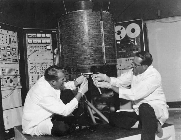
Engineers work on the Early Bird satellite shortly before its launchy
Image: NASA
At the time of writing, there are more than four hundred satellites in geosynchronous orbits. Most of these satellites are commercial in nature and provide communication services of one kind or another. Others are used to monitor global weather patterns, and some are used by various governments to carry out military surveillance. Each geostationary satellite lies directly above a fixed point on the equator at an altitude of approximately 35,786 kilometres, giving it an orbital speed of 3.07 kilometres per second and an orbital period of one sidereal day.
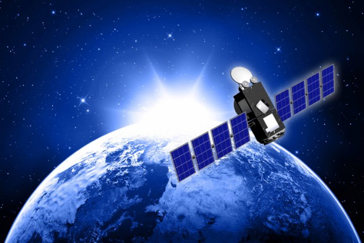
A communications satellite is essentially a microwave repeater in space. Microwave signals are sent by one or more Earth-based transmitting stations to the satellite, which processes the received signals and retransmits them to one or more Earth-based receiving stations. The Earth-based stations are collectively known as Earth stations. The link between a transmitting Earth station and the communications satellite is known as the uplink. The link between the satellite and a receiving Earth station is known as the downlink.
A communications satellite is a microwave repeater in space
The use of geosynchronous orbits for communications satellites has the advantage that the satellite always maintains the same position in the sky. This means that transmitting Earth station can use a parabolic antenna (usually called a dish antenna) to focus the uplink signal into a relatively narrow beam that is aimed at the satellite. Once set up to point directly at the satellite, little or no further adjustment is required.
The same is true of the antennae used to receive signals from the satellite, which will also be parabolic antennae aimed at a geostationary satellite. The downlink signals are directed into a feedhorn positioned at the antenna's focal point. The feedhorn is essentially a waveguide that gathers the signals and guides them to an electronic sensor connected to a low-noise block downconverter (LNB). The function of the LNB is to convert the microwave signal received from the satellite into a radio frequency signal that can be sent via a coaxial cable to satellite receiving equipment such as a set-top box (in the case of satellite TV).
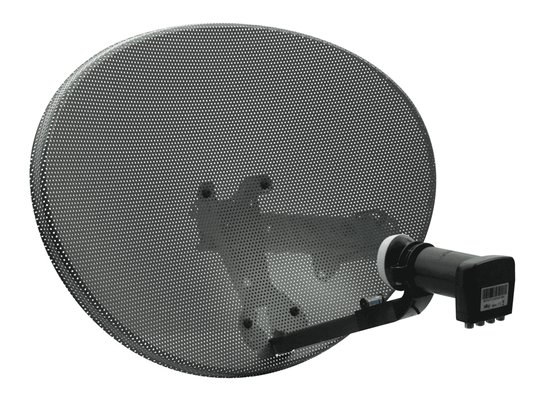
A 44 centimetre diameter satellite dish of the kind used to receive satellite TV
The critical components of a communications satellite include receiving and transmitting antennae and an array of transponders. A transponder is a sub-system that connects a receiving antenna with a transmitting antenna. Each transponder is tuned to a specific channel in an uplink frequency band. Its job is to convert the received signal to the frequency used by the corresponding downlink channel, amplify the converted signal, and send it to the transmitting antenna. The time taken for a signal transmitted by one Earth station to be received (via the satellite) by another Earth station is known as the propagation delay, and is approximately 0.24 seconds.
The earliest frequencies allocated for satellite communication fall within both the S-band (2 to 4 gigahertz) and the C band (4 to 8 gigahertz), although the satellites that use these frequencies are generally referred to as C band satellites. Most C band satellites receive uplink signals at frequencies of between 5.925 and 6.425 gigahertz, and transmit downlink signals at frequencies of between 3.7 and 4.2 gigahertz. Using different frequencies for the uplink and downlink prevents the signals retransmitted by the satellite from interfering with the signals received on the uplink.
The frequencies used for the downlink signals are always lower than those used for the uplink signals due to power considerations. The satellite's power supply comes from batteries that are kept charged by solar panels mounted on the satellite. The amount of power available to generate downlink signals is thus somewhat limited, which means that they will suffer more atmospheric attenuation than the uplink signal, which is considerably stronger. The downlink uses lower frequencies because they are less susceptible to atmospheric attenuation.
Microwave frequencies are used for satellite communication because they are not absorbed or reflected by the Earth's ionosphere, unlike the lower frequencies used for radio communications. The specific frequencies used for the uplink and downlink signals have been selected to in order to make use of regions within the microwave band for which atmospheric attenuation is relatively low.
C band satellites have in the past been used for satellite TV, although the parabolic antennae needed to receive C band signals were large (2.5 to 3.5 metres in diameter), expensive, and often rather unsightly. Most satellite TV services now use the K u band (11.2 gigahertz to 14.5 gigahertz), which enables a much smaller parabolic antenna to be used with satellite receivers.
Geostationary satellites are used for both direct broadcast satellite TV and cable TV. In both cases, signals are transmitted to the satellite on behalf of broadcasters via an uplink facility owned by the satellite operator or some third party agency. In the case of direct broadcast services, the downlink signal is sent to a satellite receiver at the subscriber's premises via a wall- or roof-mounted satellite dish. In the case of cable TV, the downlink signal is sent to a somewhat larger satellite dish at a head-end facility owned by the cable operator. From there, it is distributed to local subscribers using copper or fibre optic links.
Geostationary satellites are used for direct broadcast satellite TV and cable TV
As well as providing direct broadcast services for television and radio, geostationary satellites can be used for point-to-point and point-to-multipoint data links. The satellite can serve as the relay for a very small aperture terminal (VSAT) wide area network, in which a single Earth station acts as the hub for multiple clients that can use relatively small and inexpensive dish antennae to receive data. The potential applications for VSAT networks include telephony, data communication, and Internet services for both private and business users that promise high data rates at relatively low prices.
Geostationary satellites are used by meteorological services to monitor weather conditions on Earth and relay the data they collect to receiving stations on the ground, which send the data to various meteorological and weather forecasting facilities. They are also used to provide navigational services such as the global positioning system (GPS), which provides geographical location and time information for ships, aircraft, and mobile users.
Not all communication satellites are in geostationary orbit. At latitudes of greater than 81 degrees (essentially, the Earth's polar regions), these satellites cannot be seen. In order to provide satellite coverage for these regions, a number of satellites in highly elliptical "Molnya" orbits (named after the series of Russian military and civilian communications satellites that first used these orbits) are used. A Molnya orbit allows a satellite to spend most of its time above either the northern or southern hemisphere.
A number of low Earth orbit (LEO) satellites can also be used to implement satellite communication systems that provide global coverage. These satellites, as the name suggests, operate at much lower altitudes than geostationary satellites (between 200 and 2,000 kilometres), and are consequently far less costly to place in orbit. They also have a much shorter propagation delay, and are not subject to as much atmospheric attenuation.
On the down side, a LEO satellite has a much shorter orbital period than a geostationary satellite because of its low altitude. This means that it moves across the sky at a relatively high speed, and does not stay within range of a receiving Earth station for very long. In order to maintain a continuous service, a number of GEO satellites must be used in the same orbit. The satellites are spaced at regular intervals to form an orbital "chain" around the Earth. As each GEO satellite starts to move out of range for a particular ground station, it hands over control of the link to the next GEO satellite in the chain.
In order to provide full global coverage, several chains of LEO satellites are used to create a "constellation" of satellites. At any given time, at least one of the satellites in the constellation will be within range for any point on the Earth's surface. In order to implement the handoff procedure, as each satellite moves out of range of a ground station and is replaced by the next, as well as to coordinate and update configuration data, the satellites in a constellation must necessarily communicate with each other.
Inter-satellite communication takes place using the K a band of microwave frequencies (26.5 gigahertz to 40 gigahertz). The relatively high frequencies allow high data rates to be achieved, whilst inter-satellite signals do not interfere with the uplink and downlink signals, which usually make use of the lower frequencies in the K u band. The high susceptibility of K a band signals to atmospheric attenuation is not an issue, since even satellites in relatively low orbits are beyond those layers of the Earth's atmosphere that contain significant levels of atmospheric gases (the thermosphere extends from about 90 kilometres to anywhere between 500 and 1,000 kilometres, but air density is so low that most of this layer is normally considered to be outer space).
The first major communications system to use LEO satellites was the Iridium communications service, launched in 1998, which was a commercial failure due to the high cost to consumers of services and equipment and its overall poor performance. Between 2017 and 2019, the original Iridium constellation was completely replaced and ground-based infrastructure upgraded to form the Iridium NEXT network, which will be used by the US Department of Defense for communications and military surveillance purposes.
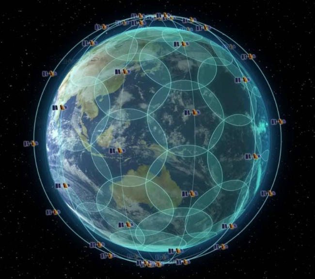
The Iridium constellation currently consists of 66 operational LEO satellites at an altitude of 780 kilometres
Image: IridiumWhere.com
Wireless network channels
Wireless networking (often referred to as Wi-Fi) is now an integral part of most home and local area networks. It is also widely available to just about all mobile users, who can now access the Internet on their smartphone, tablet, or notebook computer using wireless access points that provide free or paid Internet access. Most schools, colleges and universities provide wireless Internet access to students and staff. Many shops and restaurants, as well as hospitals, airports, and most forms of public transport, also provide wireless Internet access.
The protocols used for wireless communication are defined by the IEEE 802.11 family of wireless computer networking standards, which are maintained by the Institute of Electrical and Electronics Engineers (IEEE). These standards define several microwave frequency bands that can be used for wireless networks, each of which is subdivided into a number of individual wireless channels. The bandwidth of each channel, and the channel spacing between the individual channels, can vary considerably, as we shall see.
We should also point out that each country applies its own regulations when it comes to wireless network frequency allocation, and the way in which the various frequency ranges may be used. The channel numbers allocated to specific frequency ranges can also vary from one part of the world to another. IEEE defines several frequency bands that can be used for wireless networking. The most widely used bands are summarised in the table below.
Each frequency band consists of multiple channels, each of which has a frequency of at least 20 MHz. The various standards allow for two or more channels to be bonded together to form wider channels. For bonded channels, the centre frequency is taken to be that of the bonded group as a whole. Much of the spectrum allocated for use with wireless networks coincides with frequency bands allocated, either on a worldwide or regional basis, for industrial, scientific and medical use (these are known as the ISM bands).
| Band | IEEE Standards | Description |
|---|---|---|
| 900 MHz | 802.11ah |
This band is comprised of a number of unlicensed sub-gigahertz microwave sub-bands. It is suitable for non-commercial, relatively low data rate wireless applications that may require the additional range achievable at these frequencies. The frequencies and channel bandwidths used are specific to a particular country or region.
In Europe, 802.11ah devices operate within a single 863-868 MHz sub-band, with channel bandwidths of either 1 or 2 MHz. In the United States, three sub-bands are defined: 902-904 MHz, with channel bandwidths of 1 or 2 MHz; 904-920 MHz, with bandwidths of 1, 2, 4, 8 or 16 MHz; and 920-928 MHz, with bandwidths of 1, 2, 4 or 8 MHz. All of the 900 MHz channels in the US fall within an ISM band centred on 915 MHz, and only available in North, Central and South America. |
| 2.4 GHz | 802.11b/g/n/ax |
The 2.4 GHz band is a 95 MHz frequency band (2.401 - 2.495 GHz) comprised of 14 channels, each of which has a bandwidth of 22 MHz. The centre frequencies of channels 1 to 13 are spaced 5 MHz apart, which means there is a considerable amount of overlap between adjacent channels (see below). The centre frequencies of channels 13 and 14 are spaced 12 MHz apart.
Most countries in the world use channels 1 to 13, the notable exceptions being the United states, which uses channels 1 to 11 only, and Canada, which uses channels 1 to 12. The only country that uses channel 14 is Japan, and then only for the 802.11b standard. Most of the 2.4 GHz channels fall within the 2.45 GHz ISM band, which is available worldwide. |
| 3.6 GHz | 802.11y | This is a 40 MHz wide band of frequencies (3655 - 3695 MHz) that is only used in the United States, where it tends to be used in specialised applications rather than mainstream wireless networking. The band can be split into eight 5 MHz channels, four 10 MHz channels, or two 20 MHz channels. |
| 5 GHz | 802.11a/h/j/n/ac/ax |
The 5 GHz band offers up to 30 non-overlapping 20 GHz channels, although availability and usage may be restricted, depending on regional regulatory requirements. Some of these channels fall within the internationally recognised 5.8 GHz ISM band (5725 - 5875 MHz), and all of them appear to be available in Europe. Usage is restricted in other parts of the World, most notably mainland China and Indonesia. Currently, the 5.8 GHz ISM band may not be used in Japan, Israel, Turkey or South Africa.
The 5 GHz band provides higher data rates than the 2.4 GHz band thanks to its high frequencies, but provides less coverage because the higher frequencies cannot penetrate solid objects like walls and floors, limiting its range. The main advantage of the 5 GHz band apart from its higher data rates is that it is less susceptible to interference - there are more channels, the channels do not overlap, and there are far fewer other devices competing for the same bandwidth. Higher bandwidth channels can also be achieved by combining 2, 4, or 8 of the 20 MHz channels to create 40 MHz, 80 MHz or 160 MHz channels respectively (see below). |
| 60 GHz | 802.11ad/ay |
The 60 GHz Wi-Fi band (also known as WiGig) covers the frequency range 57.24 - 70.20 GHz, which includes the 61 GHz ISM band (61.0 - 61.5 GHz), and provides a total of six 2.16 GHz channels numbered from 1 to 6 (currently most 802.11ad devices only use channels 1 to 4). Due to the high frequencies involved, transmission range is limited, and signals are blocked by obstacles such as walls and floors. On the other hand, the high frequencies enable very high (multiple gigabit) data rates.
The 802.11ay standard is a proposed extension to 802.11ad that will quadruple the channel bandwidth to 8.64 GHz by bonding four of the 2.16 channels together, and extend the range to up to 500 metres. The potential applications for WiGig include the provision of wireless replacements for some parts of the network backbone that currently rely on guided media like copper or fibre. It is unlikely to replace 2.4 GHz or 5 GHz in mainstream Wi-Fi applications in the foreseeable future. |
The 2.4 GHz frequency band is one of the two most widely used Wi-Fi bands, the other being the 5 GHz band. Active wireless devices operating in close proximity to one another on the same channel will obviously be competing with each other for the same bandwidth, which means that data rates and performance for individual users will be adversely affected. Switching to an adjacent channel does not solve the problem either, since channel spacing is in most cases limited to 5 MHz and each channel requires a bandwidth of 22 MHz. The way in which channels 1 to 14 overlap one another is illustrated below.
Channel overlap in the 2.4 GHz Wi-Fi band
As you can see from the illustration above, the only way to avoid overlap between channels is to leave three or four channels free between the channels used. This can be achieved using channels 1, 6, and 11 (this is the most widely used configuration), or channels 2, 7, and 12. This would leave a gap of 3 MHz between the non-overlapping channels. Channel 14 should not be used, although the reasons for this given by various sources are somewhat vague. The most likely explanation is that it would interfere with other devices that use the same range of frequencies.
Most wireless routers will select a channel automatically. Channel 6 seems to be the default for many routers; otherwise the router will usually select the channel with the lowest level of interference - a process known as dynamic frequency selection (DFS). Note that, in the 5 GHz band, dynamic frequency selection is especially important because many radar systems use frequencies in the C band (4 to 8 gigahertz). The router can detect active radar devices and select a channel with a different centre frequency. If a user has manually selected a channel that is likely to interfere with a radar device, the router may disable the channel.
In larger networks, where wireless access is provided in multiple locations for a large number of users, wireless access points (or WAPs), each of which will be connected to the fixed network infrastructure via a cable, will be mounted at strategic locations. The power output from each WAP will probably be significantly greater than that of a typical home networking wireless router. In order to prevent neighbouring WAPs from interfering with one another, channels are often assigned to them manually by a network administrator.
The other frequency band currently widely used for Wi-Fi is the 5 GHz band. There are currently some thirty non-overlapping 20 MHz channels available in this band. The channel numbers, frequency ranges and centre frequencies of the channels available in Europe are listed below, along with the restrictions applicable to each channel (a brief explanation of the terms and abbreviations used follows the table).
| Channel no. | Frequency range (MHz) | Centre frequency (MHz) | Restrictions on usage |
|---|---|---|---|
| 32 | 5150–5170 | 5160 | Indoors/TPC |
| 36 | 5170–5190 | 5180 | Indoors/TPC |
| 40 | 5190–5210 | 5200 | Indoors/TPC |
| 44 | 5210–5230 | 5220 | Indoors/TPC |
| 48 | 5230–5250 | 5240 | Indoors/TPC |
| 52 | 5250–5270 | 5260 | Indoors/DFS/TPC |
| 56 | 5270–5290 | 5280 | Indoors/DFS/TPC |
| 60 | 5290–5310 | 5300 | Indoors/DFS/TPC |
| 64 | 5310–5330 | 5320 | Indoors/DFS/TPC |
| 68 | 5330–5350 | 5340 | Indoors/DFS/TPC |
| 96 | 5470–5490 | 5480 | DFS/TPC |
| 100 | 5490–5510 | 5500 | DFS/TPC |
| 104 | 5510–5530 | 5520 | DFS/TPC |
| 108 | 5530–5550 | 5540 | DFS/TPC |
| 112 | 5550–5570 | 5560 | DFS/TPC |
| 116 | 5570–5590 | 5580 | DFS/TPC |
| 120 | 5590–5610 | 5600 | DFS/TPC |
| 124 | 5610–5630 | 5620 | DFS/TPC |
| 128 | 5630–5650 | 5640 | DFS/TPC |
| 132 | 5650–5670 | 5660 | DFS/TPC |
| 136 | 5670–5690 | 5680 | DFS/TPC |
| 140 | 5690–5710 | 5700 | DFS/TPC |
| 144 | 5710–5730 | 5720 | DFS/TPC + SRD (25 mW) |
| 149 | 5735–5755 | 5745 | SRD (25 mW) |
| 153 | 5755–5775 | 5765 | SRD (25 mW) |
| 157 | 5775–5795 | 5785 | SRD (25 mW) |
| 161 | 5795–5815 | 5805 | SRD (25 mW) |
| 165 | 5815–5835 | 5825 | SRD (25 mW) |
| 169 | 5835–5855 | 5845 | SRD (25 mW) |
| 173 | 5855–5875 | 5865 | SRD (25 mW) |
Key to terms and abbreviations:
- Indoors - must be used indoors only.
- Transmit power control (TPC) - ensures that average power output is within regulatory limits in order to prevent different wireless networks from interfering with one another.
- Dynamic frequency selection (DFS) - a Wi-Fi channel allocation scheme designed to prevent interference with other devices using C band frequencies, such as radar and satellite communication.
- Short-range devices (SRD) (25 mW) - these wireless network devices are limited to a maximum transmitted power output of 25 milliwatts effective radiated power (ERP). This limits their effective range to a few hundred metres or less in order to minimise the possibility of them interfering with other wireless devices.
In addition to the non-overlapping 20 MHz channels, a number of 40, 80 and 160 MHz channels are available, each of which occupies 2, 4, or 8 20 MHz frequency ranges within the 5 GHz band. Channel 46, for example, is a 40 MHz channel that occupies the same range of frequencies as channels 44 and 48 combined (5210 – 5250 MHz). The channel number used for each of these "wide channels" reflects the relationship between the centre frequency of the wide channel and those of the 20 MHz channels whose bandwidth it occupies.
Note that using these wide channels increases the chance of interference between adjacent wireless access points; they should generally only be used in situations where the access points are distributed fairly sparsely. Note also that many client devices do not support channels wider than 20 MHz. Indeed, most home wireless routers only allow 20 MHz channels to be selected.
| Channel no. | Frequency range (MHz) | Centre frequency (MHz) | Restrictions on usage |
|---|---|---|---|
| 34 | 5150–5190 | 5170 | Indoors/TPC |
| 38 | 5170–5210 | 5190 | Indoors/TPC |
| 46 | 5210–5250 | 5230 | Indoors/TPC |
| 54 | 5250–5290 | 5270 | Indoors/DFS/TPC |
| 62 | 5290–5330 | 5310 | Indoors/DFS/TPC |
| 102 | 5490–5530 | 5510 | DFS/TPC |
| 110 | 5530–5570 | 5550 | DFS/TPC |
| 118 | 5570–5610 | 5590 | DFS/TPC |
| 126 | 5610–5650 | 5630 | DFS/TPC |
| 134 | 5650–5690 | 5670 | DFS/TPC |
| 142 | 5690–5730 | 5710 | DFS/TPC + SRD (25 mW) |
| 151 | 5735–5775 | 5755 | SRD (25 mW) |
| 159 | 5775–5815 | 5795 | SRD (25 mW) |
| Channel no. | Frequency range (MHz) | Centre frequency (MHz) | Restrictions on usage |
|---|---|---|---|
| 42 | 5170–5250 | 5610 | Indoors/TPC |
| 58 | 5250–5330 | 5290 | Indoors/DFS/TPC |
| 106 | 5490–5570 | 5530 | DFS/TPC |
| 122 | 5570–5650 | 5610 | DFS/TPC |
| 138 | 5650–5730 | 5690 | DFS/TPC + SRD (25 mW) |
| 155 | 5735–5815 | 5775 | SRD (25 mW) |
| Channel no. | Frequency range (MHz) | Centre frequency (MHz) | Restrictions on usage |
|---|---|---|---|
| 50 | 5170–5330 | 5250 | Indoors/DFS/TPC |
| 114 | 5490–5650 | 5570 | DFS/TPC |
Most wireless routers and access points are now dual-band devices that operate in both the 2.4 GHz and the 5 GHz bands, and can switch between the two depending on the prevailing conditions and network requirements. The 2.4 GHz band generally provides better coverage, but the 5 GHz band achieves much higher data rates. The range and data rate actually achievable for a given Wi-Fi channel will depend on the Wi-Fi standard, the frequencies used, the distance between the transmitter and receiver, and various environmental factors.
A Linksys dual-band wireless router
Bluetooth
Bluetooth technology is designed to provide wireless communication between fixed and mobile devices over short distances - typically, just a few metres. It was originally conceived by Dr. Jaap Haartsen, a Dutch engineer who worked in the mobile phone division of the Swedish telecommunications company Ericsson, in 1994. The idea was to replace the RS-232 cables used to connect peripheral devices like mice and keyboards to the serial ports on a personal computer with short-range, low-power wireless links. The frequencies used range from 2.4 to 2.485 GHz, and fall within the 2.45 GHz ISM band.
Since 1998, the development of Bluetooth standards and the licensing of Bluetooth technologies and trademarks to equipment manufacturers has been overseen by the Bluetooth Special Interest Group, or Bluetooth SIG, a standards organisation whose membership includes representatives from literally thousands of companies offering Bluetooth enabled products. Its most influential members today include Ericsson, IBM, Intel, Nokia, Toshiba, Microsoft, Lenovo and Apple. The latest Bluetooth version at the time of writing is Bluetooth 5.2, which offers data transfer speeds of up to 2 Mbps and a range of up to 240 metres. All Bluetooth versions are backwardly compatible with earlier versions.
Bluetooth is today used to provide short-range wireless connectivity for myriad computing and communication devices, including desktop and mobile computers, smartphones, printers, digital cameras, headsets, loudspeakers, game consoles, audio devices, and of course mice and keyboards. A network consisting of two or more such devices that communicate with each other using Bluetooth technology is sometimes referred to as a personal area network (PAN).
A Bluetooth wireless keyboard and mouse together with USB Bluetooth dongle
Virtually all modern mobile computing devices (smartphones, tablets, notebook computers etc.) and many of the newer desktop computers are now equipped with a Bluetooth transceiver that allows them to connect to other Bluetooth-enabled devices. Even older desktop computers and laptops that do not have a built-in Bluetooth capability can achieve this functionality with the simple addition of a USB Bluetooth dongle.
A Bluetooth network is called a piconet. The piconet consists of one master Bluetooth device and one or more (up to a maximum of 255) slave devices, all of which must be within radio range of the master device (typically 10 metres or less, although this can vary). At any given time, only seven slave devices may be active in the piconet. It is also possible to create a networks of two or more piconets called a scatternet, whereby a master device in one piconet is also a slave device in another. By definition, as we shall see, a Bluetooth device cannot be a master in more than one piconet.
Three Bluetooth piconets - Piconet 1 and Piconet 2 form a scatternet
At any given moment, all of the devices in a piconet will be using the same frequency. They do not interfere with one another, because time division multiplexing (TDM) is used to ensure that at any one time, the master device is only communicating with a single slave device. The subject of TDM is dealt with in more detail elsewhere, but in this instance it essentially means that each slave device is allocated a time slot during which it may communicate with the master device. The master communicates with each slave in turn, on a round-robin basis.
The main role of the master device is to set up the initial connection to one or more slave devices, and to provide timing and configuration information to those devices. The roles of master and slave can often be reversed. For example, the hands-free use of a mobile phone whilst driving (now mandatory in many countries) may require the use of a Bluetooth headset. The headset may act as the master device in order to set up the initial connection with the mobile phone, but will subsequently operate as the slave device in the relationship.

A Bluetooth headset allows hands-free use of a mobile phone whilst driving
It may have occurred to you that Bluetooth networks use the same range of frequencies as Wi-Fi networks. Indeed, these frequencies are also used by devices such as cordless telephones and baby monitors, and of course by other Bluetooth networks - all of which are potential sources of interference. To get around this problem, Bluetooth uses a radio technology called frequency-hopping spread spectrum (FHSS). To understand how this works, we need to first look at how Bluetooth transmits data, and how it uses the available bandwidth.
The first thing to note is that Bluetooth is a packet-based technology. The data to be transmitted is broken down into small chunks of data, each of which will become the payload of a single packet (the maximum payload of each packet will be determined by the Bluetooth version used). Control information, including a preamble, an access code, header information and an error correction code, is added to each chunk of data to complete the packet.
The next thing we'll talk about is the Bluetooth channels themselves. There is a version of Bluetooth known as Bluetooth Low-Energy (BLE) that is specifically designed to work with low-power devices - typically small battery-powered devices such as watches and fitness monitors - which splits the available bandwidth into 40 channels, each 2 MHz wide. We'll concentrate here, however, on the technologies collectively referred to as Bluetooth Classic, in which the Bluetooth band is split into 79 channels, each 1MHz wide, with centre frequencies at 1 MHz intervals, starting at 2.402 gigahertz.
Frequency-hopping means that, instead of using just one channel to transmit data, Bluetooth uses all 79 channels - but only one at a time! The channel used changes 1600 times per second, which means that each channel is allocated a time slot with a duration of 625 µs. The order in which the channel numbers are used determined using a pseudo-random sequence based on the 48-bit MAC address of the master device. This sequence, together with the necessary timing information, is sent by the master device to each slave device when a piconet is established so that all of the participating devices know when, and on what frequency, they may send and receive data.
Bluetooth data packets may occupy 1, 3 or 5 time slots. For single slot packets, the master transmits in even slots and receives in odd slots, while the slave receives in even slots and transmits in odd slots. Packets that occupy 3 or 5 slots complicate things somewhat, but the master will only ever transmit in an even slot, whereas the slave will only ever transmit in an odd slot. A Type field in the header of each packet contains information that includes the number of slots used to transmit the packet.
The rapid changes in frequency means that if there is interference on a particular channel, it will only affect a single time slot. If a packet is lost due to interference, the error-checking code in the packet's header allows the receiving device to detect the error and request retransmission of the affected packet.
A Bluetooth piconet switches channels 1600 times per second
Many Bluetooth devices use adaptive frequency hopping (AFH) which can determine whether a channel is currently being used by another device such as a Wi-Fi device or cordless phone and remove that channel from the pseudo-random sequence. Interference from other Bluetooth networks is rare, simply because any other active piconets will also be using frequency-hopping, and the chance of the same channel being used by two piconets during the same time 625 µs time slot is negligible.
The distance over which Bluetooth devices can communicate varies according to a number of factors, the most significant of which is their power output. Class 1 devices, for example, have a maximum power output of 100 mW (20 dBm) which gives them a theoretical maximum range of 100 metres. The current device classifications, together with the corresponding power outputs and ranges, are summarised in the table below.
| Class | Maximum power output | Maximum range |
|---|---|---|
| 1 | 100 mW (20 dBm) | ~100 m |
| 1.5 | 10 mW (10 dBm) | ~20 m |
| 2 | 2.5 mW (4 dBm) | ~10 m |
| 3 | 1 mW (0 dBm) | ~1 m |
| 4 | 0.5 mW (-3 dBm) | ~0.5 m |
Most of the Bluetooth devices currently on the market will be class 2 devices; class 1 devices are usually found only in industrial use cases. Bear in mind that the distance over which two devices can communicate effectively will be determined by the device with the lowest power output. It will also depend on the environment in which the devices are operating. The maximum range specified by a manufacturer for a given device is invariably the line-of-sight range. If obstacles such as walls, floors and ceilings are encountered, the effective range will be significantly reduced.
Most Bluetooth devices have the ability to modify their transmitted power output in accordance with the requirements of a particular link. A power level sufficient to maintain the link is selected, based on a Received Signal Strength Indicator (RSSI) reading. This prevents the transmitted signal from interfering unnecessarily with other devices, and at the same time conserves the power of the transmitting device's battery. If the RSSI reading changes, power output can be adjusted accordingly.
The way in which a connection is created between two Bluetooth devices depends on the Bluetooth version used, the types of Bluetooth devices involved in the link, and the kind of services they offer. A peripheral device such as a wireless mouse or keyboard often communicates with a computer via a USB wireless dongle provided by the manufacturer. User intervention is not normally required when setting such a device up. Once the dongle is plugged into one of the computer's USB ports and the device is turned on, the connection will be set up automatically (note that the actual Bluetooth connection is between the peripheral and the USB dongle; the computer simply sees a USB device).
Other connections between Bluetooth devices will require varying degrees of user intervention in order to confirm the identity of the devices. Ensuring that the connection is secure usually involves a process known as Secure Simple Pairing (SSP), following which an encrypted connection may be established between two Bluetooth devices. The pairing process creates a secret key called a link key that is shared between the two devices, which are then said to be paired or bonded. The link key is subsequently used to authenticate the devices to each other. Each time data is exchanged, a temporary encryption key is derived from the link key that is then used to encrypt the data.
Prior to Bluetooth version 2.1, the pairing process involved the use of a PIN code. For devices such as headsets where alphanumeric input is obviously not an option, the PIN code was often hard-wired into the device. For other devices, the same PIN code had to be entered by the user on both devices. This method of pairing was not particularly secure, however, as the PIN had to be transmitted from one device to the other for the purposes of identification, and was thus vulnerable to interception.
As a prerequisite for SSP, each device must have both a private key which is known only to that device and is never disclosed, and a public key which is transmitted in the clear and can be read by any other device. Each device in the pairing process will thus have the other's public key and their own private key. Each device can then us a well-known key derivation function to calculate a Diffie-Hellman key (DH key), named after Whitfield Diffie and Martin Hellman - two of the inventors of public key cryptology. Given two key pairs A and B, the key derivation function f will calculate the DH key as follows:
DH key = f (Public A, Private B) = f (Public B, Private B)
Only the two devices to which A and B belong will be able calculate the same DH key, which is then used as a seed for calculating the link key. Once two devices have been paired, they are usually able to connect to one another automatically without further intervention from the user. Note, however, that although a single Bluetooth device can be paired with any number of other Bluetooth devices, many devices can only be connected to one other device at a time. In order to connect to a different device, any existing connection must be terminated.
Cellular radio
Cellular radio technology is used for mobile communications. It's what you are using when you use your mobile phone to call someone or use data roaming to access the Internet. The name is slightly misleading, since the frequencies used for cellular radio are actually what we would consider to be microwave frequencies. The frequencies used, and how they are shared by multiple users, will depend on the cellular technology in use. You might be forgiven for thinking that all of the users in a cellular network are using the same technology, but that is far from being the case.
Although the basic principles underlying cellular networks have not changed significantly since mobile communication made the switch from analogue to digital in the early 1990s, the technology used to implement them has evolved considerably, driven by the exponential growth in the number of users and the demand for mobile Internet services. In 2019, there were approximately 7.9 billion active mobile subscriptions worldwide - almost one subscription for every person on the planet!
The first mobile networks were analogue. People who needed mobile communications would have a radio telephone installed in their car (these were referred to as "car phones", for obvious reasons). The phones themselves were bulky, heavy, and consumed a considerable amount of power which they obtained from the vehicle's battery. Leaving the car phone switched on whilst you were away from the vehicle often resulted in a flat battery.
The power requirement was a consequence of the distance over which communication took place, which could be tens of kilometres. The network relied on a relatively small number of powerful omnidirectional transmitting and receiving antennae (or transceivers), each of which occupied a fixed location and covered a roughly circular area of between 60 and 80 kilometres in diameter. This central antenna relayed voice data between the mobile users within its coverage area and the public switched telephone network (PSTN) to which it was connected.
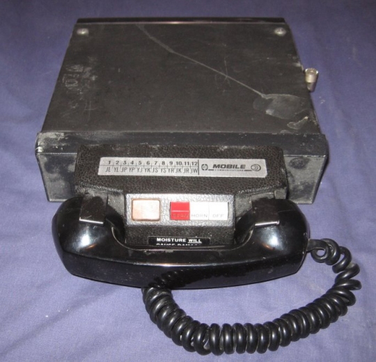
Car phones were bulky, heavy, and consumed a lot of power
The number of mobile network subscribers was relatively low, partly due to cost considerations - car phones were expensive to buy and install - but also because the number of channels available for a given area was limited. These mobile radio telephones were, however, the predecessors of the first generation (1G) of cellular mobile telephones. The networks they utilised, which included the Mobile Telephone Service (MTS), Improved Mobile Telephone Service (IMTS), and Advanced Mobile Telephone System (AMTS), are thus sometimes referred to as pre-cellular or zero generation (0G) systems.
In cellular networks, instead of one large area being covered by a single powerful transceiver, many much smaller areas called cells are used, each with its own fixed transceiver, called a base station. The base station is usually connected to the public telephone network and data networks via the fixed infrastructure of the cellular network. The transmitter power output of the base station is regulated so that signals only reach the mobile devices active within the transceiver's cell. Because all of the mobile users in a cell are close to the transceiver, they can use relatively inexpensive hand-held battery-powered devices.
Cellular networks consist of cells, each of which is served by one or more base stations
Each base station in a cell can support some maximum number of channels, depending on the type of air interface used and other factors. Reducing the size of the cells means that more cells can be used in a given geographical area, which in turn means that more channels are available for subscriber use. Small cells tend to be used in metropolitan areas where there are likely to be large numbers of users in a small geographical area. Reducing cell size has the added benefit of reducing the transmitter power output requirements of both the base station and the mobile device.
The first generation (1G) of cellular networks was primarily intended to provide voice telephony services to mobile users. The air interface was analogue in nature, and used frequency-division multiple access (FDMA) to split the available bandwidth into individual channels. Different sets of frequencies were used in adjacent cells, but the transmitted power output of base stations and mobile devices could be adjusted so that channels in cells that were sufficiently far apart could use the same frequencies without interfering with one another, thus making efficient use of network bandwidth. This is known as frequency re-use.
Subsequent generations of cellular networks, from the 2G networks of the 1990s through to the 5G networks currently being rolled out for the 2020s, have been entirely digital affairs. Each generation has brought new advancements in terms of speed, capacity and the range of services available. The technology used to implement the air interface between a mobile device and a base station - primarily the multiple access and modulation techniques used -has also changed with each new generation.
The increasing demand for bandwidth, which is due both to the phenomenal growth in the number of mobile subscribers and the vast and growing range of network services offered, has inevitably led to a significant increase in the frequency allocation needed for mobile networks. The frequency bands currently used in the UK by mobile network operators to deliver their 2G, 3G, 4G and 5G mobile services range from 800 MHz up to 3.4 GHz. As the demand for bandwidth continues to grow, we can expect to see further allocations, many involving much higher frequencies. In Europe, for example, the 26 GHz band (24.25 - 27.5 GHz) has already been earmarked for commercial deployments from 2020 onwards.