Synchronous vs. Asynchronous Transmission
Overview
When one device in a communication system wishes to send data to another device, it usually does so by sending a sequence of bits, each of which represents either a binary one or a binary zero, over a serial communications channel. The binary representation of values other than one or zero requires some number of bits to be grouped together. An octet (more commonly called a byte) is a group of eight bits that can represent simple data types such as alphanumeric characters and control codes. By stringing enough bytes together, we can represent just about any kind of data imaginable, from simple text and numeric data to high definition movies.
How we move these bytes from one place to another depends on what sort of data they represent, and how much data there is to send. If we are intermittently sending small amounts of data consisting of just a few bytes, we can transmit the bytes one after another without worrying too much about things like timing. This is essentially what happens when we use a computer keyboard to write an email, enter data into a spreadsheet, or fill in an online form. The keyboard sends each keystroke to the computer in the form of a scan code that identifies which key was pressed.

A computer keyboard sends keystrokes to the computer asynchronously
The scan code is usually between one and three bytes long, depending on which keys have been pressed and the sequence in which the keystrokes occur. Some keys do not produce an output in their own right, but modify the action of another key if both keys are pressed at the same time. These modifier keys include the Shift, Ctrl, and Alt keys. For example, if we hold down the Shift key and press the “A” key, an upper case A will be displayed on the screen instead of its lower case counterpart.
What the keyboard does not do is wait for us to type a fixed number of characters or hit Enter before it sends the scan code to the computer - it sends it immediately. Once the computer receives the scan code it deals with it immediately by displaying the character entered on the screen, without waiting for further inputs. This allows us to see the information we are typing in real time (i.e. as we type it) and make corrections if necessary.
If we want to send a large amount of data over a network, there are two things to consider. First of all, it will take a certain amount of time to send the data, depending on how much data there is and the bit-rate used to transmit it. Sending the data one byte at a time is not an efficient way to transmit a large amount of data, but sending it in one huge block is also a bad idea, because it means each network link over which the data must be sent will be unavailable to other network users until the transaction is completed. Even a few seconds is a long time in networking terms.
There is another very good reason for not sending all of the data in one large block, which is that if an error were to be detected in the received data, the entire block would have to be sent again. This would be a huge waste of network resources. In order to make efficient use of the network, we break the data down into smaller, more manageable blocks. The network’s arbitration scheme will ensure that all of our data is sent, but will allocate network resources fairly so that other users get a chance to send their data as well. Furthermore, if an error is detected at the receiver, only the block containing the error needs to be re-sent.
The next thing to think about is timing. Even though we are sending our data in relatively small blocks, we are still going to be transmitting a large number of bits, one after the other. We will of course transmit the data at the same nominal bit rate as all the other devices on the network, but in order to do so we use the transmitter’s clock. Such clocks are incredibly accurate, but there is absolutely no guarantee that the receiver’s clock is ticking at precisely the same speed. Even if the two clocks have been synchronised at some point in time, even the tiniest difference in clock speed will cause them to eventually drift apart.
We thus have two possible data transmission scenarios. In the first, we are intermittently sending a small amount of data - maybe consisting of just a few bytes - as and when there is a need to do so. In this kind of scenario, speed is not usually an important consideration, so we can send the data one byte at a time. Our clock and the receiver’s clock, although independent of one another, will be ticking at the same nominal rate. The bit rate will be slow enough to allow the receiver to sample the incoming signal in the middle of each bit time without needing to synchronise its clock with the transmitter’s clock - providing, of course, the receiver detects the start of the incoming block of data.
In the second scenario, the blocks of data we are sending could contain hundreds, or even thousands of bytes, and will be transmitted at much higher data rates. The size of each block, and the speed at which the data is transmitted, will depend on the characteristics of the data network over which the data is sent, but since the receiver will need to sample the data in the middle of each bit time, timing now becomes a critical element. The receiver must - somehow - be able to synchronise its own clock with that of the transmitter.
In the first scenario we described above, the transmission of data is asynchronous. The term asynchronous can mean different things in different contexts, but here it refers to the fact that there is no need for the transmitter and the receiver to be synchronised in order for the receiver to correctly interpret the received data, and no timing information as such is passed from the transmitter to the receiver, either directly or indirectly. In the second scenario, the transmission of data is synchronous. In order to be able to determine where each incoming bit starts and ends, the receiver’s clock must somehow be synchronised with that of the transmitter.
Asynchronous transmission
As we stated above, the term asynchronous in the context of sending data over a serial communications channel means that there is no need for the transmitter and receiver to be synchronised in order for the receiver to correctly interpret the received data. The question of timing is essentially avoided, because the transmitter sends the data one byte at a time, at a relatively low data rate - typically less than 64 kbps. The receiver only needs to be alerted to the arrival of an incoming block of data in order to know when to sample each bit to determine whether it is a one or a zero.
Once the data has been read, the receiver waits for the next block of data to arrive. When no data is being transmitted, the transmission line is in an idle state, typically represented by the constant negative voltage used to represent a logic high (1). The arrival of a new character is signalled by a start bit, usually represented by the positive voltage used to represent a logic low (0). The receiver is alerted to the arrival of a new byte when it sees the negative-to-positive voltage transition. This transition is known as an edge transition because it signals the leading edge of the start bit.
The data follows the start bit, and can consist of anything from five to eight bits. The data is usually followed by a parity bit, which allows the receiver to carry out simple error-checking, and the parity bit is followed by a stop bit that signals the end of the transmission. The duration of the stop bit is typically 1.5 or 2 times that of the data bits, and its polarity must be opposite to that of the start bit. Note that the actual number of data bits sent, and whether or not a parity bit is included, is determined according to how the data link is configured.
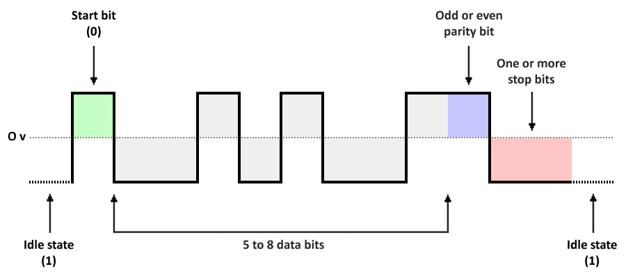
Character format in asynchronous transmission
The receiver starts counting bit times from the instant it sees the start bit’s edge transition, so it knows when to sample each of the incoming bits. Because the clocks in both the transmitter and receiver are ticking at the same nominal rate, and because the incoming block will consist of no more than ten bits plus the stop bit, the receiver should be able to sample all of the bits relatively close to the middle of each bit time. Once the transmitter has sent the stop bit, it continues to transmit the idle signal (essentially, a continuous signal at the same voltage as the stop bit) until it is ready to send the next block of data.
Asynchronous transmission is also known as start-stop mode or character mode. A block of data, referred to as a character, can contain up to eight data bits and a single parity bit. The character is framed using start and stop bits, and the resulting character frame can be transmitted independently of any other frames. Frames may be transmitted one at a time, at arbitrary intervals, or one after another in a continuous stream. In the latter case, the stop bit separating successive frames must have a duration of at least one-and-a-half bit times.
Character frames usually carry a payload of 8 bits (including the parity bit), plus the start bit and at least one stop bit, giving a minimum of 10 bits, of which at least 3 bits, or 30% of the total, are control characters. A significant proportion of the character frame block is thus overhead. Asynchronous data can be transmitted in blocks of character frames known as transmission blocks. The transmission block may contain special control characters to provide control functions, and to identify the beginning and end of a block.
The parity bit
Parity bits are used to provide limited error correction in asynchronous transmission. Generally speaking, a parity bit will enable the receiver to detect a single bit error. If one bit is corrupted during transmission, i.e. the bit is changed from a one to a zero or vice versa, the receiver will be able to discover the error by looking at the parity bit. If two or more bit errors occur - which could of course include the parity bit itself, the start bit, or one of the stop bits being “flipped” - then there is a good chance that the errors will go undetected. Statistically speaking, however, the inclusion of a parity bit will significantly increase the chances of an error being detected. So how does it work?
There are three kinds of parity - odd, even and none. The last option (none) simply means that a parity bit is not used, and no error checking is carried out. Odd parity requires the parity bit to be set to logic high (1) if the data contains an even number of ones; if the data contains an odd number of ones, the parity bit is set to logic low (0). In other words, the requirement for odd parity is that there should be an odd number of ones in the character frame, including the parity bit itself, between the start and stop bits. If a single bit gets flipped (a one becomes a zero or a zero becomes a one), then the number of ones will be even, violating the requirement and signalling that an error has occurred.
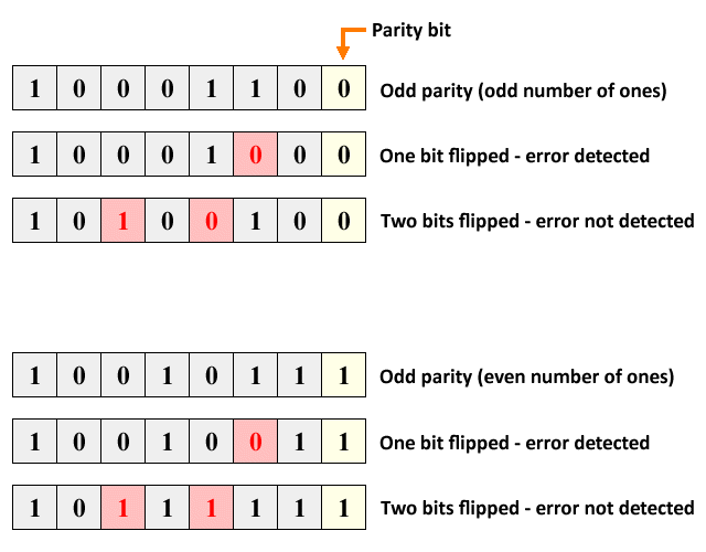
If odd parity is used, an even number of ones indicates an error
Even parity requires the parity bit to be set to logic high (1) if the data contains an odd number of ones; if the data contains an even number of ones, the parity bit is set to logic low (0). The requirement for even parity is that there should be an even number of ones in the character frame, including the parity bit itself, between the start and stop bits. If a single bit gets flipped, the number of ones will be odd, signalling that an error has occurred.
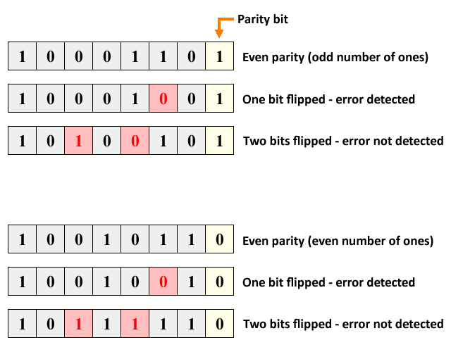
If even parity is used, an odd number of ones indicates an error
In short, the use of a parity bit, whether odd or even, will ensure that a single bit error - or any odd number of bit errors - will be result in the character frame being flagged as containing an error. Two bit errors - or any other even number of bit errors - will not be detected. This gives the receiver a slightly better than even chance overall of detecting an error condition, even if there are multiple bit errors. On the other hand, if the data bits are correct but the parity bit is flipped, an error will be indicated even though the data itself is OK.
The UART
The universal asynchronous receiver transmitter (UART) is a hardware device that, prior to the early 2000s and the arrival of the universal serial bus (USB), was used to implement asynchronous serial communication between the RS-232 serial communication (COM) ports on a computer and various peripheral devices such as the mouse, keyboard, printer and modem. Note that, on some personal computers, dedicated IBM Personal System 2 (PS/2) ports were available for the mouse and keyboard as an alternative to the standard RS-232 serial ports. PS/2 is a synchronous interface, requiring a separate clock signal between the transmitter and receiver in order to maintain synchronisation.
Today, USB ports have largely replaced both RS-232 and PS/2 serial ports on personal computers, although external devices that have an RS-232 interface can still be connected to a computer using an adapter that carries out the necessary conversion (for example, between a UART and a USB port). UARTs are far from dead and buried, however. You will typically find them being used in microcontroller applications and DIY electronics projects. They can be used, for example, to connect various types of module to a Raspberry Pi microcontroller. UARTs can exist as stand-alone integrated circuits (ICs), but are more often found inside microcontrollers.
The communication between a computer and a peripheral device such as a keyboard is usually simplex (data flows in one direction only - i.e. from the keyboard to the computer). Communication between a computer and other peripheral devices can be either half-duplex (data can flow in either direction, but not at the same time) or full duplex (data can flow in both directions simultaneously). The basic functionality of the UART is the same in either case. To understand the functionality of the UART, we’ll consider the role of the UART in a computer connected to an external modem (note that internal modems that plug into a PC’s motherboard come with their own UART).
In its role as a transmitter, the UART receives data from the sending computer via a parallel data bus, adds the start, stop and parity bits to the received data to create a character frame, and transmits the frame serially (i.e. one bit at a time) to the modem.
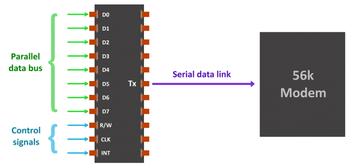
The UART creates a character frame from the data it receives and sends it to the modem
When acting as a receiver, the UART accepts an incoming character frame from the modem and checks for errors using the value of the received parity bit. If no error is detected, the UART removes the start, stop and parity bits, and transfers the remaining data bits to the receiving computer via a parallel data bus.
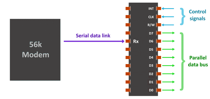
The UART removes control bits from an incoming frame and sends the data to the computer
The two-way exchange of data between two devices can essentially be accomplished (assuming no handshaking is required) using just two wires. For example, a data link can be established between two computers, A and B, using a cable called a null modem to connect the serial port on computer A with the serial port on computer B. The cable itself is essentially a standard serial cable, but with the data lines crossed over so that the transmit (Tx) pin on computer A’s UART is connected to the receive (Rx) pin on computer B’s UART, and the transmit pin on computer B’s UART is connected to the receive pin on computer A’s UART.
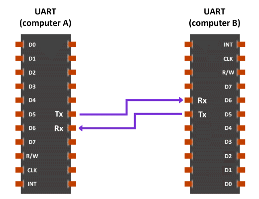
A null modem provides a serial data link between two computers
The “U” in UART stands for universal. The word is included to reflect the fact that the parameters used to transmit and receive data, which include the baud rate, the number of data bits to be sent, the number of stop bits used, and whether or not to use a parity bit (and if so, whether odd or even parity should be used) are all configurable, and can be adjusted to meet differing system requirements. The only caveat is that the transmitter and receiver must both agree on these parameters before any data is exchanged, or chaos will inevitably ensue!
The most critical issue is the baud rate, since even if both ends of a data link agree on the same baud rate, there is no guarantee that they will both transmit data at exactly the same speed because they do not share a common clock signal. Each UART generates its own clock signal, and uses it to determine the duration and frequency of the bits it transmits. It will use the same clock signal to determine when it should sample incoming bits. Therefore, although the clock signals do not have to be oscillating at the same frequency, they do have to be reasonably accurate.
In any communication system, it is usually the receiver that has the most work to do, so we’ll look at the UART’s role as a receiver first. The clock signal generated by a UART has a frequency that is typically 8, 16, or even 32 times the baud rate. Since the receiver checks the state of the incoming signal each time a clock pulse is generated, it can detect the transition from a negative to a positive voltage that signals the arrival of the start bit. Since it knows the nominal baud rate, it will then wait for the appropriate number of clock pulses before sampling the first data bit in the middle of the next bit time.
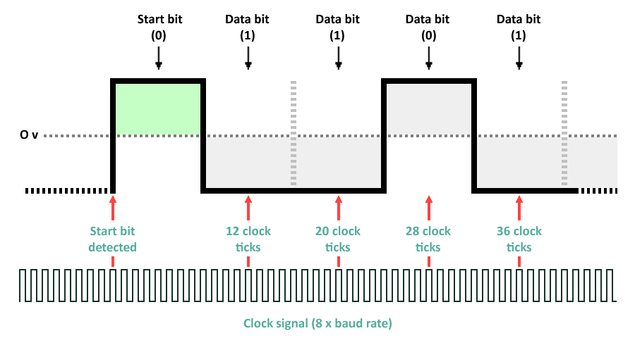
The receiver detects the leading edge of the start bit and starts counting
In the example above, the receiver’s clock is oscillating at 8 times the baud rate. When it detects the leading edge of the start bit it immediately begins counting clock ticks. After 12 clock ticks it will sample the signal to see whether the first data bit is a one or a zero, and thereafter sample at intervals of 8 clock ticks. Providing the receiver’s sampling rate is relatively close to, the baud rate used by the transmitter to output the character frame, the timing of each sample should be close to the middle of the bit time.
Note that, because asynchronous transmission has a relatively low gross bit rate, binary ones and zeros can be represented by different voltage levels, and the bit rate will thus be the same as the baud rate. It is important, however, that the receiver samples the incoming bits as close to the middle of each bit time as possible. Voltage transitions do not occur instantaneously, and if sampling occurs to close to the beginning or end of the bit time, where the voltage may be still rising or falling, the results can be inconclusive.
The receiver’s clock will be resynchronised with the incoming bit stream each time a new start bit is encountered. Depending on the type of UART in use, it may also be resynchronised each time there is a high-to-low or a low-to-high logic transition, increasing the chances of sampling the incoming bits at, or very close to, the centre of each bit time.
As each bit is read, the result (one or zero) is stored in a shift register. Once the specified number of data bits has been read, the UART will typically use status flags, or generate an interrupt, to alert the host processor that data is available to be read. Because the UART may start receiving the next character before the data stored in the shift register has been retrieved by the processor, a second shift register is normally used to provide double buffering, giving the processor more time to receive any stored data. In addition to the shift registers, some UARTs have a first-in, first-out (FIFO) memory buffer, which gives the host processor considerably more time to deal with incoming characters and preventing any data being lost.
In its role as a transmitter, the UART has a somewhat easier task because it doesn’t have to synchronise its clock with the start of an incoming character frame. When it has a character to send, it simply generates a start bit and transmits it, followed by the data bits (usually starting with the least significant bit), a parity bit if required, and one or more stop bits. The duration of each transmitted bit will be determined by the transmitter’s clock in accordance with the nominal baud rate. For a nominal rate of 9600 baud, this equates to approximately 104 µs.
The data to be transmitted is usually received from the host processor or some other internal device via a parallel data bus, and will be stored in a shift register to await transmission. As for the receive function, the UART typically provides double buffering and a FIFO memory buffer for outgoing characters. Since full-duplex operation requires the UART to be able to send and receive data at the same time, it will require separate shift registers and memory buffers for the receive and transmit functions. To avoid being overrun by incoming data, the UART may use status flags or interrupts to signal its ready status to the host processor.
Synchronous transmission
In order to transfer large amounts of data efficiently, we use high-speed data links to send transmission blocks called frames, each frame consisting of hundreds or thousands of bytes of data and a relatively small amount of control information. There are no start bits or stop bits to tell the receiver where each byte starts and ends, so the receiver sees the incoming frame as a continuous stream of bits, typically arriving at a rate of millions or even billions of bits per second.
The transmitter’s clock and the receiver’s clock must somehow be synchronised so that the receiver can sample the incoming data at the right time. In some cases, a separate clock signal can be used to enable the receiver to maintain synchronisation with the transmitter. The receiver uses the shared clock signal to sample the incoming data signal in the middle of each bit-time. Sampling is triggered by the rising and/or falling edge of each clock signal pulse.
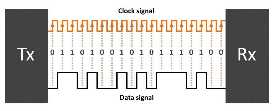
A separate clock signal provides synchronisation between transmitter and receiver
Unfortunately, unless the transmitter and receiver are in relatively close proximity, the use of a separate clock signal is not a particularly practical solution in most cases because it significantly increases bandwidth usage and makes the transmission system both more difficult and more expensive to design and implement. A better solution is to embed the timing information into the signal itself. This can be achieved using a bi-phase encoding scheme such as Manchester encoding. The embedded timing signal can be extracted from the incoming bit stream by the receiver, which uses it to synchronise itself with the transmitter.
Embedded timing
Manchester encoding, which was widely used in in 10BASE-T Ethernet networks, embeds a timing signal in a digital signal by ensuring that there is a voltage transition in the middle of each bit-time. The transition (from a positive to a negative voltage or vice versa) serves as both a clocking mechanism and as a method of encoding the data. A low-to-high transition represents a binary one, while a high-to-low transition represents a binary zero. This type of encoding is known as bi-phase encoding because a transition from one to zero or vice versa is represented by a 180° shift in the signal's phase.
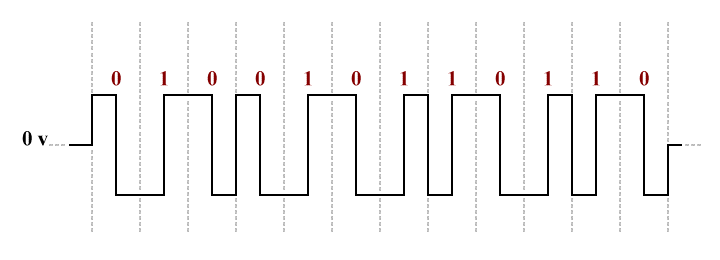
Manchester encoding is a bi-phase digital encoding scheme
At the transmitter, the data to be transmitted is sent to an encoder as a stream of bits, together with a clock signal that determines the frequency at which the encoder outputs the encoded data signal and its embedded clock signal (the line code). The receiver extracts the embedded timing information from the line code by passing the received signal through a digital phase-locked loop (DPLL). The phase-locked loop generates an output signal whose phase is related to that of the input signal.
The simplest kind of phase-locked loop consists of a variable frequency oscillator and a phase detector in a feedback loop. The oscillator generates a periodic signal, and the phase detector compares the phase of that signal with the phase of the input signal, adjusting the oscillator to keep its output in phase with the incoming signal. Keeping the phases of the input and output signals synchronised will, by definition, also keep their frequencies synchronised.
The output from the phase-locked loop is fed into the receiver’s decoder along with the incoming signal, and provides the timing information needed to decode the incoming signal correctly. The output from the decoder should be the same bit stream used by the transmitter to generate the line code. The clock signal generated by the phase-locked loop is used to ensure that the receiver samples the bit stream in the middle of each bit time (any errors in the received data due to noise or other factors will be detected and dealt with by communication protocols working at a higher level).
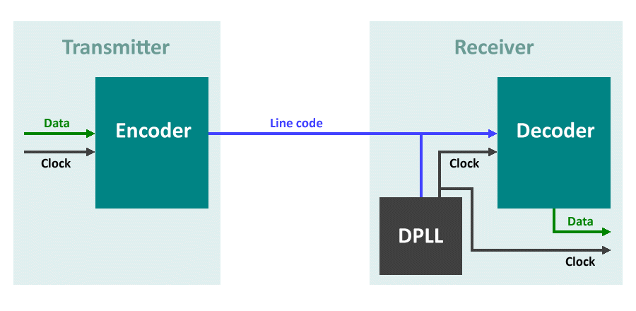
A DPLL is used to extract embedded timing information
Manchester encoding is perhaps one of the best known line coding techniques and is often used as an example of how timing information can be embedded in a baseband signal. Whilst it is well-suited for legacy 10BASE-T Ethernet applications, however, the much higher data rates found in today’s data communication and telecommunication networks require somewhat more sophisticated and more efficient (in terms of bandwidth utilisation) line coding schemes. A detailed examination of some of those encoding schemes will be undertaken elsewhere.
Bit-oriented frames
We saw that, for asynchronous transmission, data is transmitted in character mode. Each “character” consists of 5 - 8 bits plus an optional parity bit, preceded by a start bit and followed by one or more stop bits. The resulting character frame can be viewed as a stand-alone entity, even if it forms part of a transmission block. The synchronous transmission of data, on the other hand, is said to be bit-oriented. It allows blocks containing many thousands of bytes of data to be transmitted as a continuous stream of bits, and at very high data rates. This is possible because the receiver is tightly synchronised with the transmitter, either due to the presence of a separate clock signal or, more commonly, the inclusion of embedded timing information in the signal itself.
As we mentioned earlier, transmitting data as huge, monolithic blocks is an inefficient way to utilise a network, even at the very high data rates available today. Very large blocks of data are therefore broken down into smaller, more manageable blocks called frames before being transmitted over a data link. A frame is usually preceded by a unique sequence of bits called a preamble. The preamble alerts the receiver to the arrival of a frame, and enables it to synchronise itself with the transmitter.
The exact format of the frame will depend on the type of network over which the data is transmitted. The preamble is usually followed by a header consisting of control information, such as the MAC address of the transmitting node, the MAC address of the receiving node, a sequence number to enable the receiver to keep track of frames received and to re-assemble the data in the correct order, and the size of the frame’s payload. Next comes the data itself, followed by a trailer containing more control information - typically an error detection or correction code. There may also be a short postamble bit sequence to signal the end of the frame.

A bit-oriented frame
The preamble, postamble and control information in a frame typically occupies just a few bytes, whereas the data field can consist of hundreds or even thousands of bytes of data. An Ethernet frame, for example, can carry up to 1500 bytes of data, but requires just 26 bytes of overhead, including the preamble. The percentage of overhead for an Ethernet frame carrying a full payload is thus less than 2%, whereas at least 30% of an asynchronous character frame is overhead. Synchronous transmission thus makes much more efficient use of the available bandwidth.
