| Author: | |
| Website: | |
| Page title: | |
| URL: | |
| Published: | |
| Last revised: | |
| Accessed: |
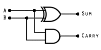
Digital computers must be able to carry out arithmetic operations such as simple addition. For computers, addition is the basis for other arithmetic functions such as subtraction and multiplication and division. The arithmetic and logic unit (ALU) within a microprocessor therefore has to have circuitry that can carry out binary addition. A simple combinational logic circuit that can add two single-digit binary numbers can be constructed quite easily using a combination of only two logic gates – an AND, and an XOR as shown below. This circuit is called a half-adder.

The half-adder
Essentially, there are three possible outcomes from adding two one-digit binary numbers. If both digits (represented by the inputs A and B) are zero, the result (represented by SUM on the diagram) will be zero. Inputs A and B are common to both of the logic gates in the circuit. If either A = 1 or B = 1 (but not both), the value of SUM will be 1. The circuit produces the correct result for SUM because the XOR logic gate will produce an output of 1 only if A = 1 or B = 1, but not if they both have the same value.
If both A = 0 and B = 0, the sum will be zero, and there will be no carry (represented by CARRY on the diagram). If both A = 1 and B = 1, the sum will still be zero, but there will be a carry to the next position. This happens because if both A = 1 and B = 1, the AND logic gate will produce an output of 1. Thus, for all possible outcomes the half-adder will produce the correct sum and carry for adding two binary digits. The truth table for the half-adder circuit is shown below.
| Inputs | Outputs | ||
|---|---|---|---|
| A | B | Sum | Carry |
| 0 | 0 | 0 | 0 |
| 0 | 1 | 1 | 0 |
| 1 | 0 | 1 | 0 |
| 1 | 1 | 0 | 1 |
In terms of practical computing, a circuit that can only add two single-digit binary numbers is of extremely limited us. It would be far more useful if we could add together two 8-digit binary numbers. This creates a problem in the sense that, once we have added the first two bits, there may be a carry to contend with from the previous bit addition. We therefore need a combinational logic circuit that will not only add two bits together and produce a sum and a carry, but can accept a carry from a previous operation and deal with it in such a way as to still produce a correct answer.
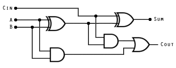
The circuit we have seen above does not provide the required functionality, hence the name "half-adder". The circuit we will now look at consists of two half-adder circuits joined by an OR gate, and is usually referred to as a "full-adder". The logic circuit for the full-adder, together with its truth table, are shown below. Note that we now have three inputs (A, B and CIN).

The full-adder
| Inputs | Outputs | |||
|---|---|---|---|---|
| A | B | CIN | SUM | COUT |
| 0 | 0 | 0 | 0 | 0 |
| 0 | 0 | 1 | 1 | 0 |
| 0 | 1 | 0 | 1 | 0 |
| 0 | 1 | 1 | 0 | 1 |
| 1 | 0 | 0 | 1 | 0 |
| 1 | 0 | 1 | 0 | 1 |
| 1 | 1 | 0 | 0 | 1 |
| 1 | 1 | 1 | 1 | 1 |
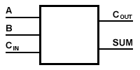
Essentially, one half-adder produces the sum and carry for A + B. The sum from this first operation is added to CIN by the second half-adder, which produces a final value for SUM. If either half-adder produces an intermediate carry, the OR gate produces a value for COUT of 1 (note that it is not possible for both half-adders in the circuit to produce an intermediate carry at the same time, so the final OR gate could in fact be an XOR gate and still produce the same result). The full-adder can be represented by a "black box" diagram to enable us to use it more easily for more complex schematics. A common representation is illustrated below.

The full-adder represented as a "black box"
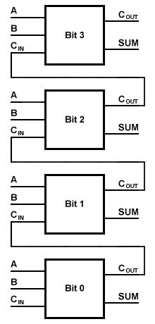
To add two 4-bit binary numbers and produce a 4-bit sum (with a carry, if required), a full adder is required for each pair of bits to be added. Each adder can accept a carry on its CIN input from the preceding bit addition, output the sum of A, B and CIN on its SUM output, and produce a carry on its COUT output to be sent to the CIN input of the next binary adder.
Binary numbers of any size may be added together using a series of full-adders chained together (see below). Each full-adder handles the addition of one corresponding pair of binary digits from each of the two numbers to be added together with any carry in from the previous addition, and produces both a sum and a carry out. The number of full-adders used depends on the size of the numbers to be added together, but is usually a binary multiple (e.g. 4, 8, 16, 32 or 64).
If the addition of two binary numbers results in a carry from the last full-adder (the one that adds the most significant bits from each number), it is called an overflow. If this occurs, an overflow flag is set to inform the processor that the result obtained from the addition is too big to be stored in the specified number of bits. The action taken will depend on the nature of the hardware and the application being used.

A 4-bit adder