| Author: | |
| Website: | |
| Page title: | |
| URL: | |
| Published: | |
| Last revised: | |
| Accessed: |
The application we are going to build here can manipulate images in various ways. It is not intended as a serious piece of image editing software (we will leave that to the professionals) but despite its limitations can produce some interesting effects. It also demonstrates quite well how images can be manipulated on a pixel by pixel basis, and how we can resize images to suit our particular needs.
The application has a display area of 640 × 480 pixels - relatively small by modern standards. Images produced by modern digital cameras tend to be much bigger. Nevertheless, the application can handle any image you care to throw at it provided it is stored as a bitmap, JPEG or GIF file. Larger images will simply be scaled down to fit the display area. Nevertheless, this is a quite powerful application considering the relatively small amount of code involved, and there is plenty of scope to extend the program's functionality.
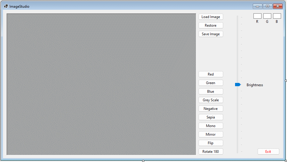
The ImageStudio program interface
| Control | Name | Additional Properties |
|---|---|---|
| Form | frmImageStudio | Size: 960, 540 Text: "ImageStudio" |
| PictureBox | picDisplay | BackColor: ControlDark BorderStyle: Fixed3D Location: 12, 12 Size: 640, 480 |
| Button | cmdLoad | Location: 658, 12 Size: 85,23 Text: "Load Image" |
| Button | cmdRestore | Location: 658, 41 Size: 85,23 Text: "Restore" |
| Button | cmdSave | Location: 658, 70 Size: 85,23 Text: "Save Image" |
| Button | cmdRed | Location: 658, 206 Size: 85,23 Text: "Red" |
| Button | cmdGreen | Location: 658, 235 Size: 85,23 Text: "Green" |
| Button | cmdBlue | Location: 658, 264 Size: 85,23 Text: "Blue" |
| Button | cmdGrey | Location: 658, 293 Size: 85,23 Text: "Grey Scale" |
| Button | cmdNeg | Location: 658, 322 Size: 85,23 Text: "Negative" |
| Button | cmdSepia | Location: 658, 351 Size: 85,23 Text: "Sepia" |
| Button | cmdMono | Location: 658, 380 Size: 85,23 Text: "Mono" |
| Button | cmdMirror | Location: 658, 409 Size: 85,23 Text: "Mirror" |
| Button | cmdFlip | Location: 658, 438 Size: 85,23 Text: "Flip" |
| Button | cmdRotate180 | Location: 658, 467 Size: 85,23 Text: "Rotate 180" |
| Button | cmdExit | ForeColor: Red Location: 857, 467 Text: "Exit" |
| TrackBar | trkBrightness | Location: 780, 12 Maximum: 20 Orientation: Vertical Size: 32, 480 Value: 10 |
| Label | lblTrackbar | Location: 818, 246 Text: "Brightness" |
| Label | lbl_xyR | AutoSize: False BackColor: White BorderStyle: FixedSingle Location: 844, 12 Size: 27, 18 Text: None |
| Label | lbl_xyG | AutoSize: False BackColor: White BorderStyle: FixedSingle Location: 877, 12 Size: 27, 18 Text: None |
| Label | lbl_xyB | AutoSize: False BackColor: White BorderStyle: FixedSingle Location: 910, 12 Size: 27, 18 Text: None |
| Label | lblR | AutoSize: False Location: 844, 30 Size: 27, 18 Text: "R" TextAlign: MiddleCenter |
| Label | lblG | AutoSize: False Location: 877, 30 Size: 27, 18 Text: "G" |
| Label | lblB | AutoSize: False Location: 910, 30 Size: 27, 18 Text: "B" |
| OpenFileDialog | ofdLoadImage | - |
| SaveFileDialog | sfdSaveImage | - |
Dim bmp01, bmp02, bmpTemp As Bitmap
Dim clr, clrTemp As Color
Dim intR, intG, intB, intTemp As Integer
The first line of code declares three variables of type Bitmap. One of these variables (bmp01) will hold a reference copy of the image being worked on, while the second (bmp02) will be used to implement changes. The reason for the third variable will become apparent later.
The second line of code declares two variables of type Color, one of which (clr) will be used to hold the result of changes to the colour of a pixel, while the second (clrTemp) will be used to hold the results of any intermediate calculations. Note that the Color data type stores each colour as a structure in which the Red (R) , Green (G) and Blue (B) values that make up the colour are represented as member variables. Each of these member variables can be individually accessed, and can be read from or written to.
The last line of code declares three integer variables that will be used to store the values of the red (intR) , green (intG) and blue (intB) colour components for a given pixel. A fourth integer variable (intTemp) will be used to hold the results of various intermediate calculations.
The next piece of code we are going to write (and the longest single procedure in the entire program) is the code to load an image.
Dim intResponse As Integer
Dim sngMul As Single
ofdLoadImage.Filter = "Bitmap Files|*.bmp|JPEG Files|*.jpg|GIF Files|*.gif"
If ofdLoadImage.ShowDialog = DialogResult.OK Then
bmp01 = New Bitmap (Image.FromFile (ofdLoadImage.FileName))
If bmp01.Width > 640 Or bmp01.Height > 480 Then
intResponse = MsgBox _
("Image is larger than display area. Do you want to resize image to fit?", _
vbYesNo + vbQuestion)
End If
If intResponse = vbNo Then
Exit Sub
ElseIf intResponse = vbYes Then
If(bmp01.Width / 4) >= (bmp01.Height / 3) Then
sngMul = 1 / (bmp01.Width / 640)
Else
sngMul = 1 / (bmp01.Height / 480)
End If
bmpTemp = New Bitmap(bmp01, (bmp01.Width * sngMul), (bmp01.Height * sngMul))
bmpTemp.SetResolution(bmp01.HorizontalResolution, bmp01.VerticalResolution)
bmp01 = bmpTemp
End If
bmp02 = New Bitmap(bmp01)
bmpTemp = New Bitmap(bmp01)
picDisplay.Image = bmp01
Me.Text = "ImageStudio(" & ofdLoadImage.FileName & ")"
End If
This is a rather complex-looking piece of code, but that complexity reflects the fact that it does quite a lot of work. The first line declares an integer variable (intResponse) that will receive the user's response to the message box that will be displayed if the target image is too big for the display area (more about this shortly). The second local variable (sngMul) is a floating-point variable that will be used to hold a calculated value. Essentially it is a multiplier that reflects the factor by which an oversized image would need to be reduced in order for the display area to accommodate it.
The next line of code sets up the file filter for the OpenFileDialog control (ofdLoadImage), which as a result will only list image files of the allowed types (Bitmap, JPEG or GIF). The rest of the code is taken up by an If . . . End If statement that only executes if the user clicks the Open button of the File Open dialog box, having of course first selected a file. That being the case, the next line of code creates a new object of type Bitmap from the image contained in the selected file, and assigns it to the variable bmp01.
The next block of code is a nested If . . . End If statement that executes if the image is too big to fit into the display area, in which case the user is given the option to resize the image to fit.
If the user answers "No", the code exits the subroutine without further ado. Otherwise, it checks the aspect ratio of the image to determine whether the image has a 4:3 (or better) width to height ratio, in which case the multiplier variable sngMul is calculated as the fraction by which the image's dimensions must be multiplied in order for it to fit into the display area. If the aspect ratio is less than 4:3, then the height is used to calculate the value for sngMul instead.
The next two lines create a new Bitmap object using bmp01, but with the new (reduced) dimensions. The result is assigned to bmpTemp, but the Visual Basic SetResolution() method is called to scale down the contents of the original image to fit into the new one. Initially, bmp01 contains the original image unchanged. Then, bmpTemp gets a scaled down version of the image, and this resized version is assigned back to bmp01.
The last four lines of code before the End If are much more straightforward. Two new bitmap objects are created from bmp01 and assigned to the variables bmp02 and bmpTemp. The picDisplay control's Image property is also set to bmp01.
Finally, the form's Text property is amended to reflect the fact that the application has now loaded, and is displaying, the contents of an image file. Run the program and load an image to see how this works (if you don't have a suitable image to hand, you can download the zipped file image_studio.zip, which contains the images featured in this page, from the following link:
The illustration below shows the application with an image loaded into the display area.
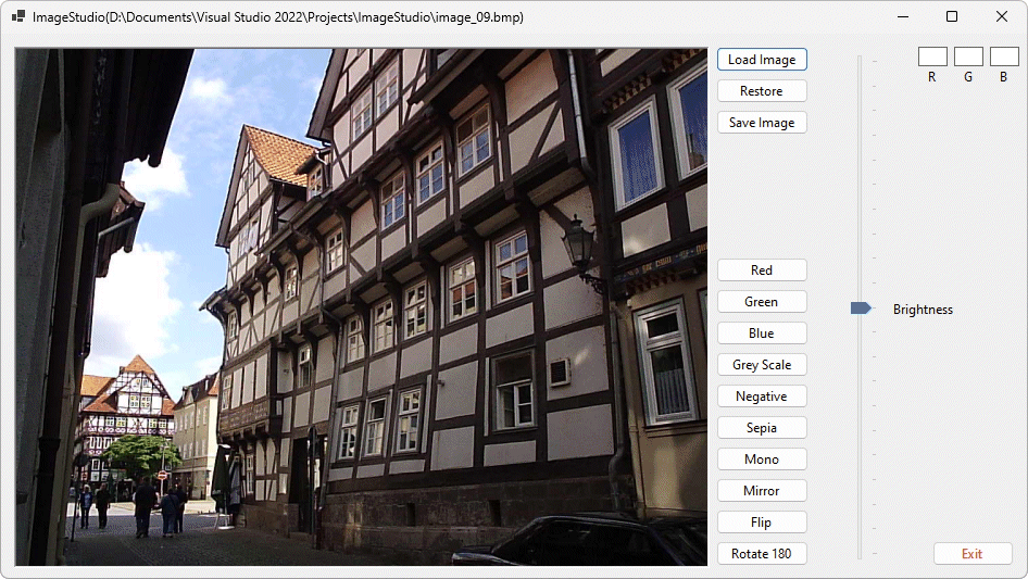
The ImageStudio program can now load an image
picDisplay.Image = bmp01
bmp02 = New Bitmap(bmp01)
bmpTemp = New Bitmap(bmp01)
trkBrightness.Value = 10
This code simply sets the displayed image back to the original image which is safely stored in bmp01. It then assigns fresh bitmap images to bmp02 and bmpTemp using the image stored in bmp01 (you will not really be able to see the effect of this code until we have done something to change the appearance of an image). Meanwhile, it might be interesting to be able to look at the Red, Green and Blue values (RGB values) of the pixels in our images . . . .
Private Sub picOriginal_MouseMove(sender As Object, e As _
Windows.Forms.MouseEventArgs) Handles picDisplay.MouseMove
If picDisplay.Image Is Nothing Then
Exit Sub
End If
If e.X < bmp02.Width And e.Y < bmp02.Height Then
clr = bmp02.GetPixel(e.X, e.Y)
lbl_xyR.Text = clr.R
lbl_xyG.Text = clr.G
lbl_xyB.Text = clr.B
Else
lbl_xyR.Text = ""
lbl_xyG.Text = ""
lbl_xyB.Text = ""
End If
End Sub
This procedure executes if the mouse moves over the picDisplay control. The first If . . . End If statement checks to see whether there is an image in the PictureBox control, and if not, exits the subroutine immediately. The first part of the subsequent If . . . Else . . . End If statement is executed if the mouse is actually over part of the image (which does not necessarily have to occupy the entire display area). It gets the colour value for the pixel under the mouse and assigns that value to the variable clr.
The values of each of the R, G and B components of clr are assigned to the Text properties of lbl_xyR, lbl_xyG and lbl_xyB respectively. If the mouse is over an area that is not occupied by part of the image, all three of these Label controls have their Text property set to a blank string (""). Run the application, load an image, and move the mouse pointer over the display area to see how this code affects the program's output.
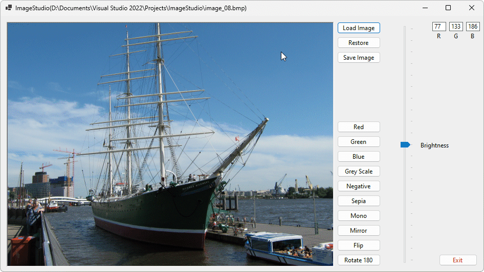
The R, G and B values for the pixel under the mouse pointer are now displayed (top right)
As you move the mouse over the image, you should see rapid changes in the values displayed for the R, G and B values of the pixel under the mouse pointer (unless you have chosen an image with a large area of one colour, of course!). There is one minor annoyance, however. When you move the mouse pointer off the image and out of the PictureBox control, the last recorded values remain displayed. In order to clear these values when the mouse is not hovering over the PictureBox control, we need a small addition to our code.
Private Sub picOriginal_MouseLeave(sender As Object, e As EventArgs) _
Handles picDisplay.MouseLeave
lbl_xyR.Text = ""
lbl_xyG.Text = ""
lbl_xyB.Text = ""
End Sub
This relatively trivial bit of code does not really need much explanation. It simply sets the Text property of the three label controls lbl_xyR, lbl_xyG and lbl_xyB to the empty string when the mouse leaves picDisplay.
We now come to the main purpose of the application which is to create interesting (if not particularly useful) graphic effects using the images we have chosen. For example, we know that the colour displayed by each pixel is the result of combining three primary colours (red, green and blue), each of which can have an intensity of between 0 and 255. We can manipulate these RGB values individually for every pixel in an image. If we want to, we can (for example) turn off the green and blue components and just leave the red component. Let's do just that!
If picDisplay.Image Is Nothing Then
Exit Sub
End If
For x = 0 To bmp02.Width - 1
For y = 0 To bmp02.Height - 1
clr = bmp02.GetPixel(x, y)
clrTemp = Color.FromArgb(clr.R, 0, 0)
bmp02.SetPixel(x, y, clrTemp)
bmpTemp.SetPixel(x, y, clrTemp)
Next
Next
picDisplay.Image = bmp02
trkBrightness.Value = 10
A common feature of many of the procedures we will write from now on is the If . . . End If statement at the beginning of the code that exits the procedure immediately if there is no image to process. The remainder of the code in this procedure loops through every pixel in the image, one column at a time, using nested For . . . Next loops. The colour value for each pixel is retrieved and stored in the variable clr using GetPixel() (one of the methods available to a Visual Basic object of type Bitmap).
The variable clrTemp is then passed the value of just the red component of clr using the method Color.From Argb(), in which the green and blue arguments have been set to zero. The SetPixel() method of the Bitmap object is then called upon twice, once to set the value of the pixel in bmp02 to the new colour (a shade of pure red), and once to perform the same operation on the corresponding pixel of bmpTemp (essentially making bmpTemp a copy of bmp02).
The penultimate line sets the displayed image to the new version of bmp02, while the last line resets the position of the Trackbar control's slider (in case we have moved it meanwhile). Run the program again, load an image, and click on the Red button to see the result. The screenshots below show "before and after" views for this feature of the application. If you look carefully at the second picture, you will notice that the RGB values displayed in the top right hand corner show zero values for the green and blue components (the intensity value displayed for the red component varies as you move the mouse around over the image) .
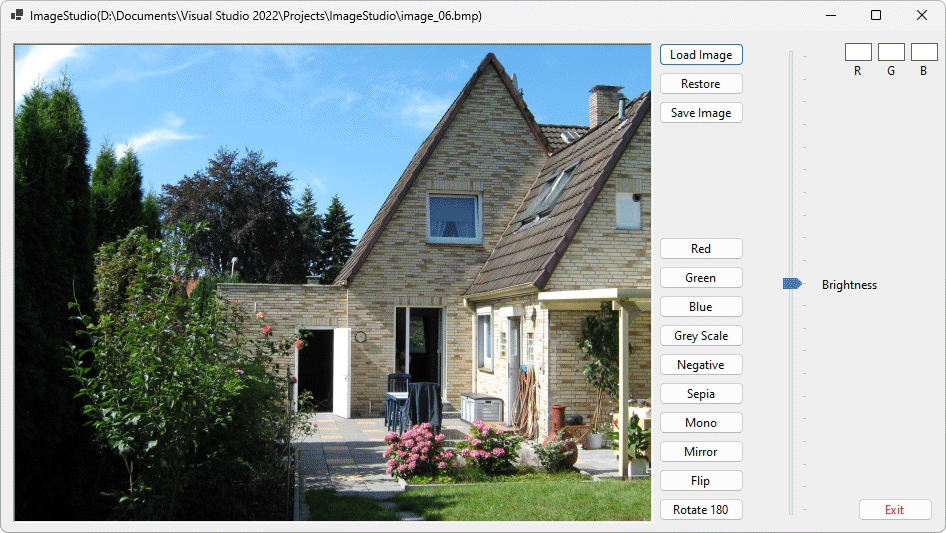
An image with no transformations
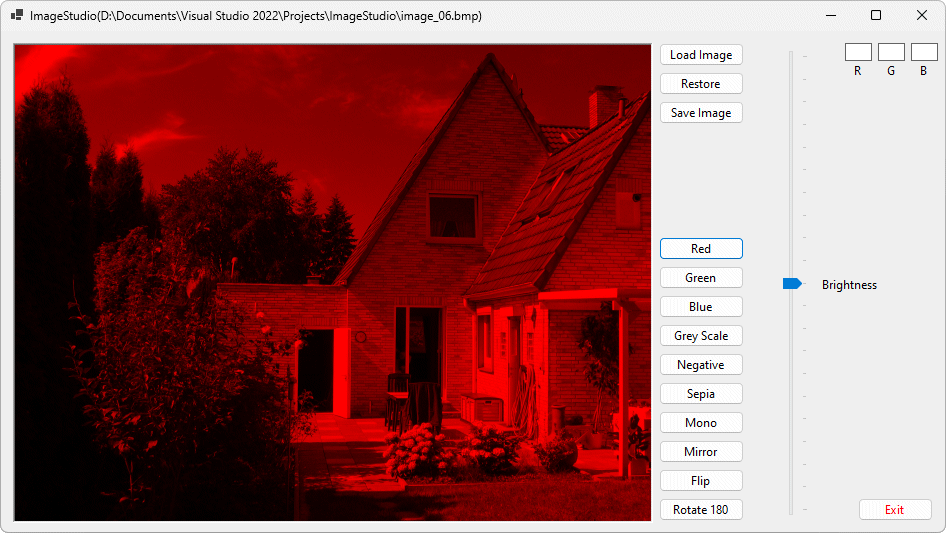
The same image after the red filter has been applied
If picDisplay.Image Is Nothing Then
Exit Sub
End If
For x = 0 To bmp02.Width - 1
For y = 0 To bmp02.Height - 1
clr = bmp02.GetPixel(x, y)
clrTemp = Color.FromArgb(0, clr.G, 0)
bmp02.SetPixel(x, y, clrTemp)
bmpTemp.SetPixel(x, y, clrTemp)
Next
Next
picDisplay.Image = bmp02
trkBrightness.Value = 10
If picDisplay.Image Is Nothing Then
Exit Sub
End If
For x = 0 To bmp02.Width - 1
For y = 0 To bmp02.Height - 1
clr = bmp02.GetPixel(x, y)
clrTemp = Color.FromArgb(0, 0, clr.B)
bmp02.SetPixel(x, y, clrTemp)
bmpTemp.SetPixel(x, y, clrTemp)
Next
Next
picDisplay.Image = bmp02
trkBrightness.Value = 10
The purpose of the Grey Scale button is to transform the image from a colour image to its greyscale equivalent (sometimes greyscale versions of photographs can be used quite effectively). In computer graphics, shades of grey can easily be created by setting each of the R, G and B components to the same value. At the extreme ends of this scale you have black (R=0, G=0 and B=0) and white (R=255, G=255 and B=255) Anything in between is some shade of grey, although as you approach values that are close to either end of the scale, it becomes quite difficult for the human eye to differentiate.
The main problem here is that the colours in the image will have different values for the red, green and blue elements (otherwise they would already be grey!). What value do we therefore use for our R, G and B components to create the correct shade of grey? The solution we have come up with (which is not necessarily the only method that could be used) is to take the average intensity of the three colour components and then apply it to all of them to create a grey shade. The code is shown below and is fairly self explanatory, providing you understood the code we used to filter out colours in the procedures already implemented for the Red, Green and Blue buttons.
If picDisplay.Image Is Nothing Then
Exit Sub
End If
For x = 0 To bmp02.Width - 1
For y = 0 To bmp02.Height - 1
clr = bmp02.GetPixel(x, y)
intR = clr.R
intG = clr.G
intB = clr.B
intTemp = (intR + intG + intB) / 3
clrTemp = Color.FromArgb(intTemp, intTemp, intTemp)
bmp02.SetPixel(x, y, clrTemp)
bmpTemp.SetPixel(x, y, clrTemp)
Next
Next
picDisplay.Image = bmp02
trkBrightness.Value = 10
The main difference in coding here is that we are extracting all of the colour values, adding them together and dividing by three in order to get the average value. The value thus obtained is then used to create a new colour that is a shade of grey (by assigning the same value to each of the R, G and B components) and then writing that new colour back to the corresponding pixels in bmp02 and bmpTemp.
Run the program, load an image, and click on the Grey Scale button to see the result. The screenshots below show "before and after" views as before. If you look carefully at the second picture, you will notice that the RGB values displayed in the top right hand corner show identical values for the red, green and blue components.
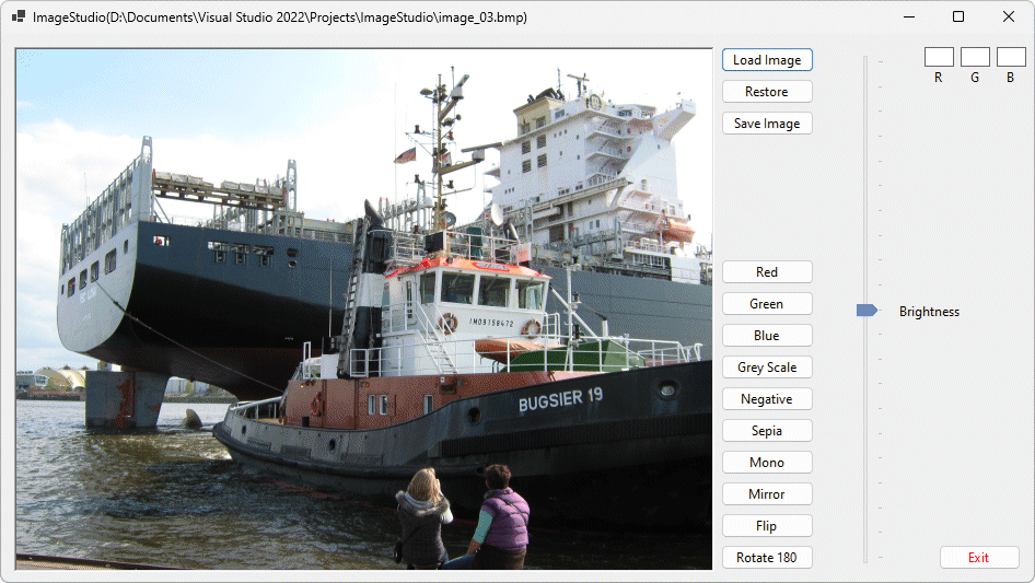
An image with no transformations
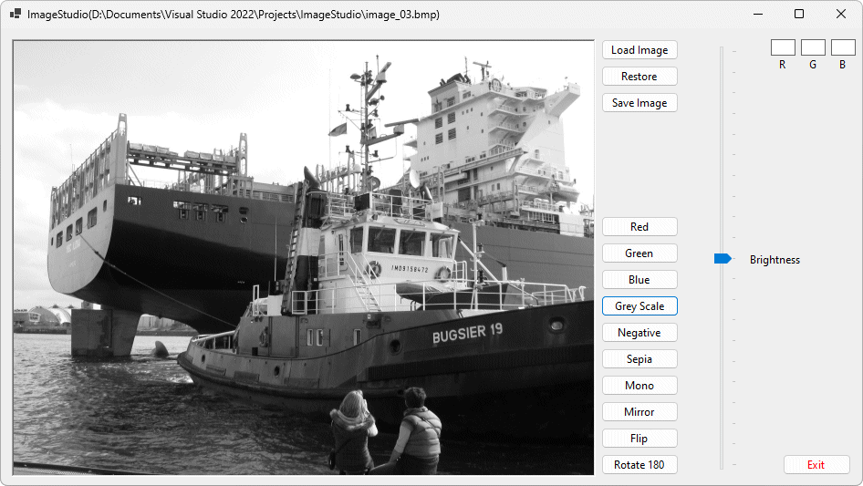
The same image after the greyscale filter has been applied
The next procedure we shall write will create a negative image (you may have seen photographic film negatives of colour or monochrome photographs). This procedure alters the value of each colour component within each pixel by subtracting the value of each element from its maximum possible value (255) in order to effectively shift it to the opposite end of the spectrum for that element. Apart from that - if you understood the previous procedure - little further explanation is necessary.
If picDisplay.Image Is Nothing Then
Exit Sub
End If
For x = 0 To bmp02.Width - 1
For y = 0 To bmp02.Height - 1
clr = bmp02.GetPixel(x, y)
clrTemp = Color.FromArgb(255 - clr.R, 255 - clr.G, 255 - clr.B)
bmp02.SetPixel(x, y, clrTemp)
bmpTemp.SetPixel(x, y, clrTemp)
Next
Next
picDisplay.Image = bmp02
trkBrightness.Value = 10
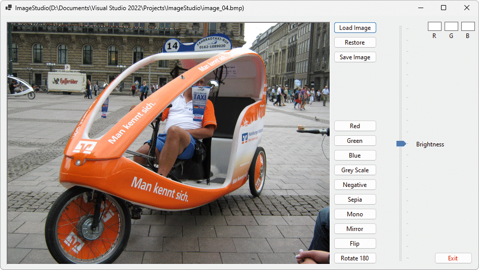
An image with no transformations
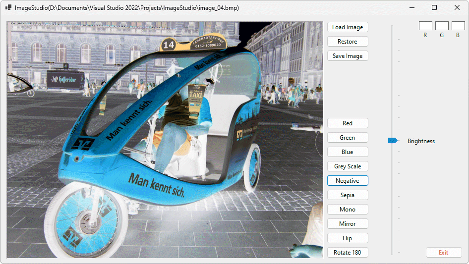
The same image after the negative filter has been applied
Note that again, we make no claims as to the correctness of this procedure in producing a true negative image, but it seems to work well enough. Note also that the various transformations can be applied in series - the illustration below shows the effect of first transforming the image to greyscale and then applying the negative filter to the result. Combining transformations in this way can produce some very interesting results!
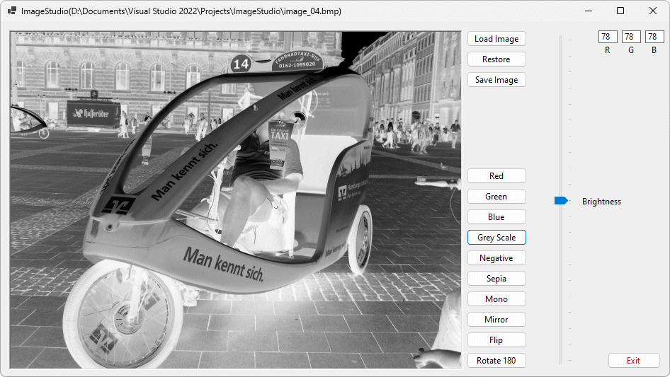
The same image again, after both greyscale and negative filters have been applied
The next button we come to is Sepia. This time we are definitely walking on disputed territory, as the proffered definitions of what constitutes "sepia" vary widely. The overall effect is intended to produce (artificially) the same kind of effect as is seen in very old "black and white" (read greyscale) photographs that have been affected over time by exposure to light. You may well have seen examples, in which the image has turned from shades of grey to shades of a sort of orange-brownish colour (again, my description is based on my own personal perceptions).
The algorithm used in the code offered here is based on "colour degradation" values found on various graphics-oriented websites and forums that occasionally discuss this issue, and the basis for it is somewhat abstract. It does, however, appear to work quite effectively. Essentially, the code has the effect of lightening the image slightly overall, while at the same time adjusting the value of each of the red, green and blue components based on a fixed ratio of their pre-existing values and that of the other components.
As far as I have been able to work out, the effect is to reduce the available colour spectrum (a bit like the greyscale algorithm) while favouring red and green (in that order) over blue (if anyone has a concise, simple explanation for how it works, I would be happy to hear from them!)
If picDisplay.Image Is Nothing Then
Exit Sub
End If
For x = 0 To bmp02.Width - 1
For y = 0 To bmp02.Height - 1
clr = bmp02.GetPixel(x, y)
intR = (clr.R * 0.393) + (clr.G * 0.769) + (clr.B * 0.189)
intG = (clr.R * 0.349) + (clr.G * 0.686) + (clr.B * 0.168)
intB = (clr.R * 0.272) + (clr.G * 0.534) + (clr.B * 0.131)
If intR > 255.0 Then intR = 255.0
If intG > 255.0 Then intG = 255.0
If intB > 255.0 Then intB = 255.0
clrTemp = Color.FromArgb(Int (intR), Int (intG), Int (intB))
bmp02.SetPixel(x, y, clrTemp)
bmpTemp.SetPixel(x, y, clrTemp)
Next
Next
picDisplay.Image = bmp02
trkBrightness.Value = 10
Because some of the transforms may leave individual colour components with values in excess of 255, the code includes statements that will limit the values of the R, G and B components to a maximum of 255. Run the program, load an image, and click on the Sepia button to see the result. The screenshots below show "before and after" views as before. You can make your own mind up as to the effectiveness of this procedure.
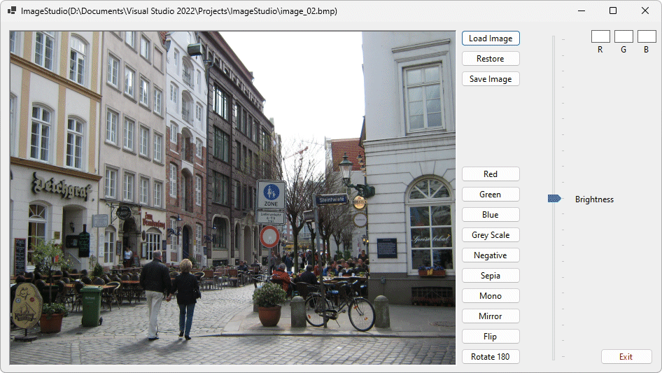
An image with no transformations
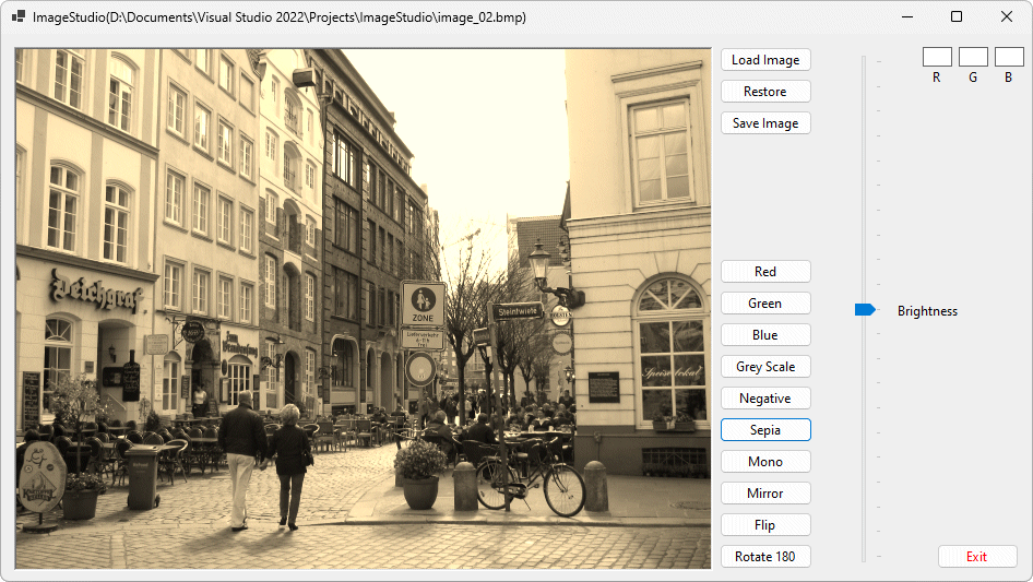
The same image after the sepia filter has been applied
We are back on slightly firmer ground with the Mono button, which produces a genuinely black and white image in the sense that the resulting images only has black and white pixels. The code is very similar to the greyscale code except that this time, if the average of the colour component values equates to less than 64 the pixel is set to black; otherwise it is set to white. Again, we do not proffer this as the only solution, but it seems to work reasonably well.
If picDisplay.Image Is Nothing Then
Exit Sub
End If
For x = 0 To bmp02.Width - 1
For y = 0 To bmp02.Height - 1
clr = bmp02.GetPixel(x, y)
intR = clr.R
intG = clr.G
intB = clr.B
intTemp = (intR + intG + intB) / 3
If intTemp < 64 Then
clrTemp = Color.Black
bmp02.SetPixel(x, y, clrTemp)
bmpTemp.SetPixel(x, y, clrTemp)
Else
clrTemp = Color.White
bmp02.SetPixel(x, y, clrTemp)
bmpTemp.SetPixel(x, y, clrTemp)
End If
Next
Next
picDisplay.Image = bmp02
trkBrightness.Value = 10
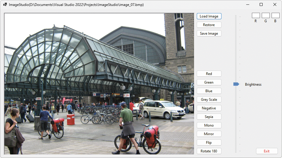
An image with no transformations
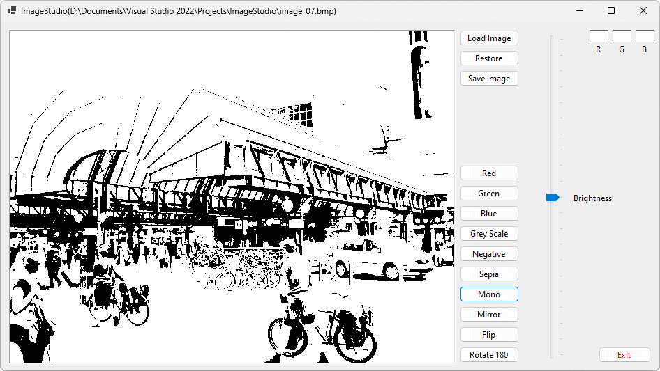
The same image after the mono filter has been applied
The next procedure (invoked by the Mirror button) creates a mirror image of the image loaded into the display area. The procedure again loops through the pixels column by column, but this time it swaps the colours in the pixels in the left and right halves of the screen, starting from the outside edges and working towards the centre until all of the pixels have had their colours swapped. The algorithm itself is actually relatively straightforward, although it looks complicated at first glance.
If picDisplay.Image Is Nothing Then
Exit Sub
End If
For x = 0 To (bmp02.Width / 2) - 1
For y = 0 To bmp02.Height - 1
clrTemp = bmp02.GetPixel(x, y)
clr = bmp02.GetPixel((bmp02.Width - x) - 1, y)
bmp02.SetPixel(x, y, clr)
bmp02.SetPixel((bmp02.Width - x) - 1, y, clrTemp)
bmpTemp.SetPixel(x, y, clr)
bmpTemp.SetPixel((bmp02.Width - x) - 1, y, clrTemp)
Next
Next
picDisplay.Image = bmp02
trkBrightness.Value = 10
The main For . . . Next loop uses a counter with a range of 0 to (image width/2)-1. If the image has an odd number of pixels in the horizontal dimension, the centre column is left unchanged. The program has been tested on images that have both an odd and an even number of pixels in the horizontal dimension, and it seems to work correctly in both cases. Run the program, load an image, and click on the Mirror button to see the result. The screenshots below show "before and after" views as before.
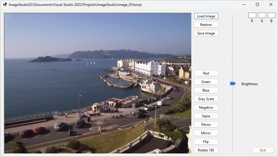
An image with no transformations
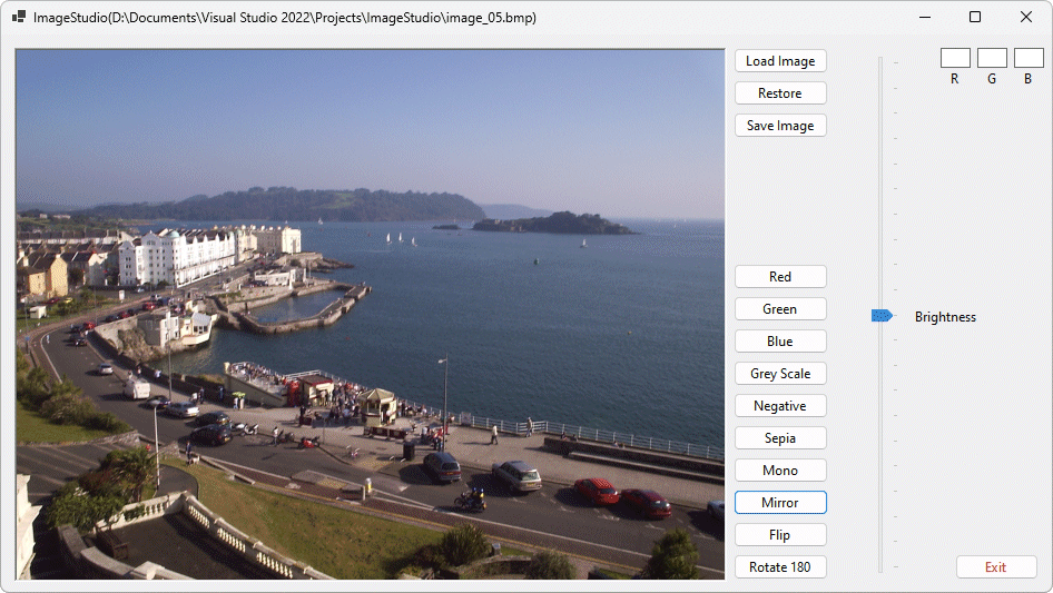
The same image after the mirror procedure has been applied
The penultimate transformation that we will code here is invoked by the Flip button. It is very similar to the mirror procedure, except that this time the image is inverted rather than mirrored. There is still a symmetrical exchange of colour values between pixels, but now it takes place across the horizontal centreline between the top and bottom halves of the image rather than between the left and right halves. The code is therefore very similar, and works in pretty much the same way.
If picDisplay.Image Is Nothing Then
Exit Sub
End If
For x = 0 To bmp02.Width - 1
For y = 0 To (bmp02.Height / 2) - 1
clrTemp = bmp02.GetPixel(x, y)
clr = bmp02.GetPixel(x, (bmp02.Height - y) - 1)
bmp02.SetPixel(x, y, clr)
bmp02.SetPixel(x, (bmp02.Height - y) - 1, clrTemp)
bmpTemp.SetPixel(x, y, clr)
bmpTemp.SetPixel(x, (bmp02.Height - y) - 1, clrTemp)
Next
Next
picDisplay.Image = bmp02
trkBrightness.Value = 10
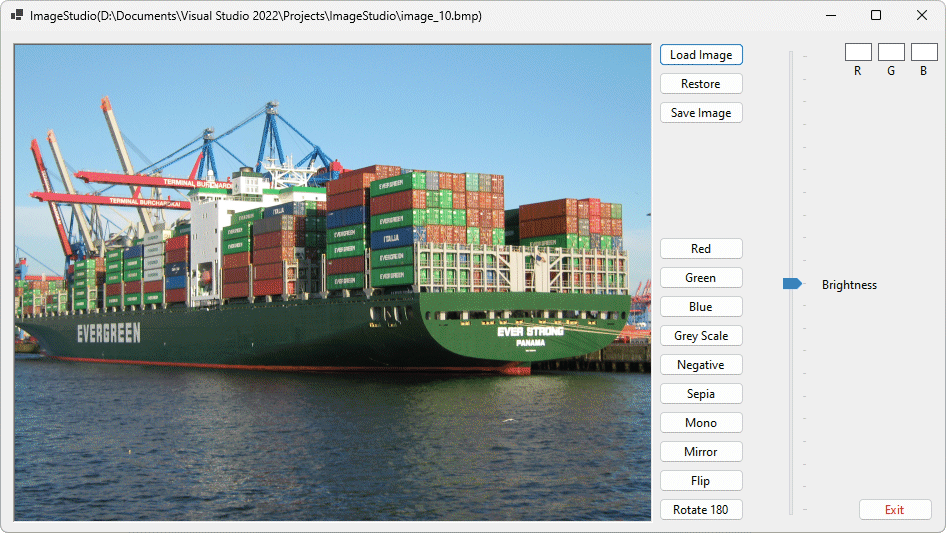
An image with no transformations
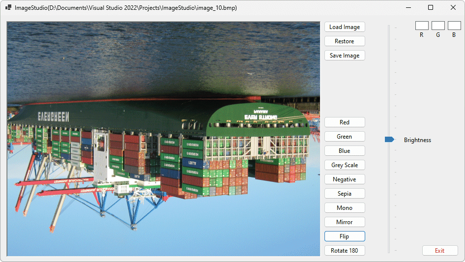
The same image after the flip procedure has been applied
The final transformation is triggered when the user clicks on the Rotate 180 button, and is a combination of the mirror and flip transformations in the sense that it rotates the image through 180 degrees. It essentially achieves, in a single operation, what applying the mirror and flip operations would achieve if applied separately one after the other. Applying the rotate 180 procedure twice (or any even number of times for that matter) restores the image to its original state.
If picDisplay.Image Is Nothing Then
Exit Sub
End If
For x = 0 To bmp02.Width - 1
For y = 0 To (bmp02.Height / 2) - 1
clrTemp = bmp02.GetPixel(x, y)
clr = bmp02.GetPixel((bmp02.Width - x) - 1, (bmp02.Height - y) - 1)
bmp02.SetPixel(x, y, clr)
bmp02.SetPixel((bmp02.Width - x) - 1, (bmp02.Height - y) - 1, clrTemp)
bmpTemp.SetPixel(x, y, clr)
bmpTemp.SetPixel((bmp02.Width - x) - 1, (bmp02.Height - y) - 1, clrTemp)
Next
Next
picDisplay.Image = bmp02
trkBrightness.Value = 10
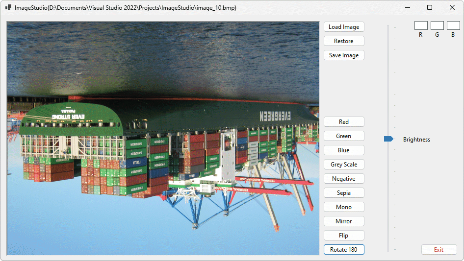
Using the same image as before, this is the effect when the rotate 180 procedure is applied
The last procedure we will write that has an effect on the image loaded into the display area is not actually a transformation as such, but it does alter the brightness of the image by increasing or decreasing the intensity of each of the RGB values in each pixel. It can also be applied to any of the effects we have used so far, at any time. The effect is intended to be temporary in the sense that the user should be able to move the slider up and down to increase or decrease brightness, but should also be able to return the image to its original state by setting the slider back to its starting position.
There could be literally hundreds of thousands of pixels in an image, each with a different colour, and each colour potentially having different values for the red, green and blue components. It is inevitable that uniformly increasing or decreasing the value of each colour component of each pixel will see some of those values exceeding 255 or at the upper end of the scale or becoming negative values at the lower end. Either situation causes a problem, so we need to impose upper and lower limits for pixel RGB component values of 255 and 0 respectively.
Although it should be possible to write a more efficient procedure to handle this situation without resorting to the use of an otherwise redundant copy of the bitmap, we have opted for an approach that is easier to code. To that end, bmpTemp (as you may have noticed) is constantly maintained as a copy of bmp02. When the brightness is increased or decreased, the pixel RGB values in bmp02 are changed with reference to their counterparts in bmpTemp, which is itself not affected by changes in brightness. Note however that any transformation applied to an image after its brightness has been changed will be applied to the current state of bmp02, and will subsequently be copied into bmpTemp) .
If picDisplay.Image Is Nothing Then
Exit Sub
End If
intTemp = trkBrightness.Value * 10
For x = 0 To bmpTemp.Width - 1
For y = 0 To bmpTemp.Height - 1
clr = bmpTemp.GetPixel(x, y)
intR = clr.R * intTemp / 100
intG = clr.G * intTemp / 100
intB = clr.B * intTemp / 100
If intR > 255 Then intR = 255
If intG > 255 Then intG = 255
If intB > 255 Then intB = 255
If intR < 0 Then intR = 0
If intG < 0 Then intG = 0
If intB < 0 Then intB = 0
clrTemp = Color.FromArgb(Int (intR) , Int (intG) , Int (intB))
bmp02.SetPixel(x, y, clrTemp)
Next
Next
picDisplay.Image = bmp02
The code loops through the image pixel by pixel, one column at a time, as before. It uses the current value of the TrackBar control to determine the factor by which to increase or decrease the intensity of each pixel's RGB components. Run the program one more time, load an image, and experiment with the trackbar control to see how it affects the image. The screenshots below show an image as it would normally appear, followed by the same image at full brightness, and then the image once more with the trackbar slider set to a value of 5 (the trackbar settings range from 0 to 20, with 10 representing the original brightness level for the image when it is loaded).
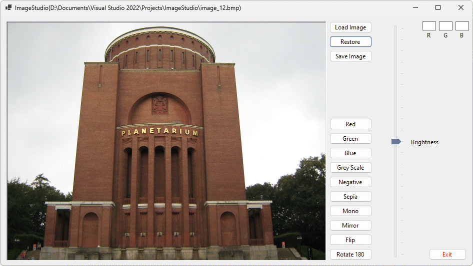
An image at its original brightness level
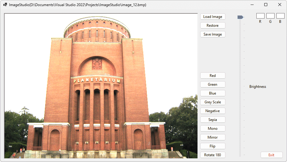
The same image at full brightness
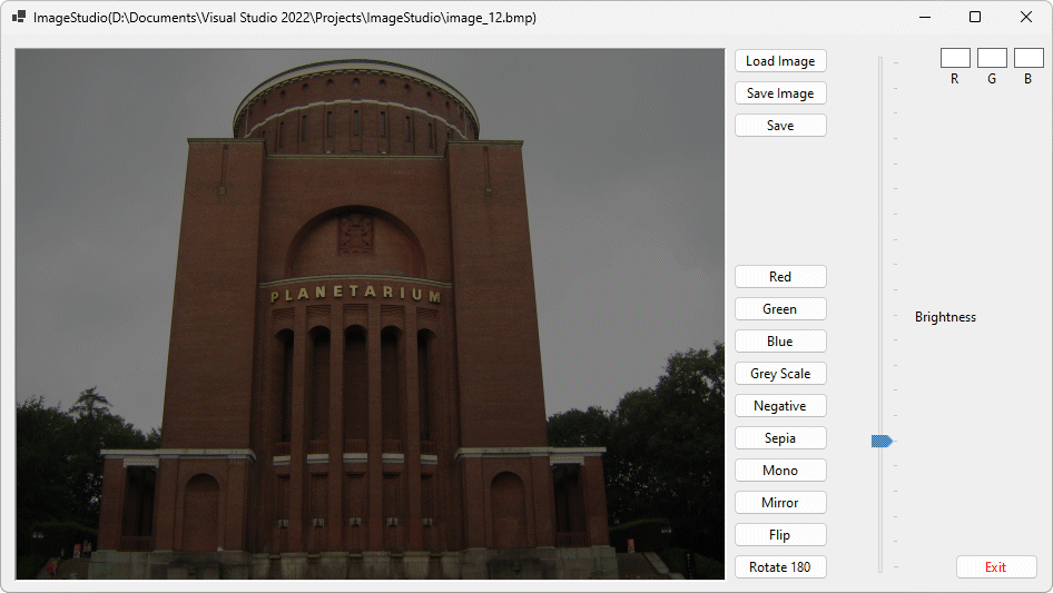
The image once more at brightness level 5
Since it would be nice to be able to save the results of the changes we have made to an image in a separate file, the last significant piece of code we will write will be the code for the Save Image button, which allows us to save the currently displayed image in a Bitmap, JPEG or GIF image file. The code calls on the SaveFileDialog control sfdSaveImage, and requires little explanation. If the user clicks OK, the code uses an If . . . ElseIf . . . End If statement to determine which file type the user has chosen, and saves the file in the appropriate format with the filename given by the user (if the user does not enter a filename, clicking on Save in the dialog box doesn't actually do anything) .
sfdSaveImage.Filter = "Bitmap Files|*.bmp|JPEG Files|*.jpg|GIF Files|*.gif"
If sfdSaveImage.ShowDialog = DialogResult.OK Then
If sfdSaveImage.FilterIndex = 1 Then
picDisplay.Image.Save(sfdSaveImage.FileName, _
Drawing.Imaging.ImageFormat.Bmp)
ElseIf sfdSaveImage.FilterIndex = 2 Then
picDisplay.Image.Save(sfdSaveImage.FileName, _
Drawing.Imaging.ImageFormat.Jpeg)
ElseIf sfdSaveImage.FilterIndex = 3 Then
picDisplay.Image.Save(sfdSaveImage.FileName, _
Drawing.Imaging.ImageFormat.Gif)
End If
End If
End
The application could be extended to do much more, and probably more efficiently. It nevertheless serves to demonstrate some of the ways in which Visual Basic can be used to manipulate graphic images, and provides a starting point for those interested in creating more sophisticated image editing applications.