| Author: | |
| Website: | |
| Page title: | |
| URL: | |
| Published: | |
| Last revised: | |
| Accessed: |
A flowchart is a way of visually representing the flow of data through an information processing system, the operations performed within the system, and the sequence in which they are performed. A program flowchart describes the sequence of operations required to solve a given problem. A programmer will often create a flowchart before writing a program.
The flowchart is drawn according to defined rules, using standard flowchart symbols. Flowcharts help us to understand the logic of complex problems, and make it easier to write programs in a high level programming language. Some commonly used flowcharting symbols are shown below.
Flowcharts are a good way of communicating the logic of a system to others, and allow problems to be analysed effectively. They can also form part of the program's documentation, and are useful for facilitating efficient coding and debugging. Flowcharts can, however, become complex and unwieldy if the program in question is large and complex. They may also need to be completely redrawn if changes are required, depending on how they have been produced.
| Symbol | Name | Description |
|---|---|---|
 |
Flowline | Lines that connect other flowchhart symbols and indicate the direction of logic |
 |
Terminal | Indicates the start or end of a task |
 |
Processing | Arithmetic or data-manipulation operations |
 |
Input/Output | Indicates an input or output operation |
 |
Decision | Decision making and branching |
 |
Connector | Used to join different parts of a program |
 |
Offpage | Indicates that the flowchart continues on another page. |
 |
Predefined | Represents a group of statements that perform some processing task |
 |
Annotation | Provides additional information about another flowchart symbol |

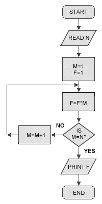
An example flowchart