| Author: | |
| Website: | |
| Page title: | |
| URL: | |
| Published: | |
| Last revised: | |
| Accessed: |
Asynchronous Transfer Mode (ATM), sometimes called cell relay, is a widely deployed, high speed, connection-oriented backbone technology that is easily integrated with technologies such as SDH, Frame Relay and DSL. A significant number of common carriers worldwide use ATM in the core of their networks. ATM uses short, fixed-length packets called cells to carry data, and combines the benefits of circuit switching (guaranteed capacity and constant transmission delay) with those of packet switching (flexibility and efficiency for intermittent traffic). ATM is more efficient than synchronous technologies such as time-division multiplexing (TDM), in which each user is assigned a specific time slot which no other station can use. Because ATM is asynchronous, time slots are available on demand. ATM was originally designed in the mid 1980s for use in public networks, but has also been deployed as the backbone technology in private networks.
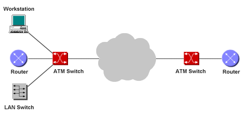
An ATM network
An ATM network is made up of ATM switches and ATM end systems (e.g. workstations, switches and routers). An ATM switch is responsible for cell transit through an ATM network. It accepts an incoming cell from an ATM end system (or another ATM switch), reads and updates the cell header information, and switches the cell to the appropriate output interface. An ATM end system contains an ATM network interface card. ATM switches support two types of interface - User-to-Network Interface (UNI) and Network-to-Network Interface (NNI). These interfaces can be further categorised as either public or private. A private UNI connects an ATM end system to a private ATM switch, while a public UNI connects an ATM end system or a private switch to a public ATM switch. A private NNI connects two private ATM switches, while a public NNI connects two public ATM switches.
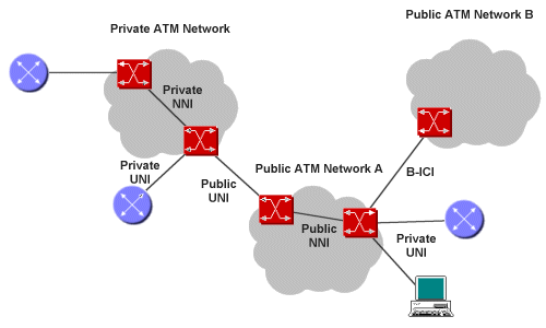
ATM interfaces in private and public networks
ATM is based on the ITU-T Broadband Integrated Services Digital Network (B-ISDN) standard, and was intended as a high-speed data transfer technology for voice, video, and data over public networks. The idea behind ATM was the utilisation of small, fixed length cells in order to reduce packet delay variation (sometimes called jitter) in the multiplexing of data streams. This is particularly important for voice traffic and other real-time applications, where the availability of a constant stream of data is essential. When ATM was first developed, optical links were considerably slower than they are today, and large data packets could take a significant amount of time to process in switching and multiplexing devices, leading to queuing delays that exceeded the acceptable maximum delay parameters for speech or video traffic. Although buffering can alleviate the problem to an extent, it requires the implementation of costly echo cancellation hardware. In addition, any significant delay on a voice channel will have a detrimental effect on the user experience.
Because it is asynchronous, ATM is more efficient than synchronous technologies such as time-division multiplexing (TDM), in which each station is assigned its own time slot. A station with a lot of data to send can only send data during the time slot allocated to it, even if all the other time slots are currently empty. On the other hand, if a station has no data to send when its time slot becomes available, the time slot remains unused, even if other stations have data to send. With ATM, time slots are available on demand.
Each cell consists of a 5-byte header and a 48-byte payload. The basic format is shown below.

The basic format of an ATM cell
An ATM header can have one of two formats - User-Network Interface (UNI) or Network-Node Interface (NNI). UNI is used for communication between end systems and switches. NNI is used for communication between switches. The header formats are shown below.
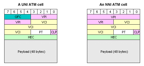
ATM UNI and NNI cell formats
The following descriptions summarise the header fields (note that the NNI header does not include the Generic Flow Control field, but has an additional four bits in the Virtual Path Identifier field, allowing for a much larger number of virtual paths to be used):
ATM networks are connection-oriented, and a virtual connection or virtual circuit must be set up between two end points in an ATM network before data can be transferred. A virtual circuit can be permanent (similar to a leased line, in that a connection is guaranteed and there is no setup procedure), or switched. A switched virtual circuit is created and released dynamically, and persists only while data is being transferred. Call set up is managed automatically. A virtual channel is the complete end-to-end link between two end systems, and will consist of a number of virtual paths. Each virtual path is a semi-permanent connection between two points in the network, and will itself consist of a number of physical transmission paths. Switches in an ATM network use a combination of Virtual Path Identifiers (VPIs) and Virtual Channel Identifiers (VCIs) to determine how to route incoming cells. The diagram below illustrates the relationship between virtual channels, virtual paths and transmission paths.

Relationship between virtual channels, virtual paths and transmission paths
ATM supports two kinds of connections. Point-to-point connections connect two ATM end-systems, and may be either unidirectional or bi-directional. Point-to-multipoint connections connect one source ATM end system to a number of destination ATM end systems, and are always unidirectional. The source ATM end system (or root node) transmits the information once only, and ATM switches replicate cells and forwards them to the various destination end systems (or leaves) wherever the connections within the network branch.
Various connection-management messages are used to set up and clear down an ATM connection. When an ATM device requires a connection to another ATM device, it sends a connection-signalling-request packet to its directly-connected ATM switch (the ingress switch). The request contains the ATM address of the destination ATM end system, together with any quality of service parameters necessary for the connection. The switch returns a call proceeding message to the source of the request, and invokes an ATM routing protocol. The request is propagated through the network, and the necessary connections are set up. The request will arrive at the switch that is attached to the destination end system (the egress switch). The egress switch forwards the request across its UNI to the destination end system, which either accepts or rejects the request. If rejected, a release message is returned and all connections are cleared. If accepted, a connect message is returned. On receipt of a connect message, the source end system sends a connect acknowledge message to the destination end system, following which data transfer may begin.
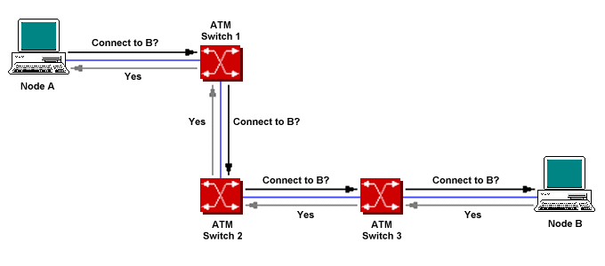
A connection request is sent through the ATM network
The ATM routing protocol routes the connection request based on the source and destination addresses, the type of service required, the traffic parameters of each data flow in both directions, and the Quality of Service (QoS) parameters requested in each direction. When a switch receives a cell from an end system or another switch, it reads the cell header information and switches the cell to the appropriate output interface. Virtual circuit information has only local significance within a switch, and the cell header is updated by each switch the cell passes through.
The Private Network-to-Network Interface (PNNI) protocol provides both topology-discovery and call-establishment services. In order for switches to set up an end-to-end connection between two end points, each switch must have some knowledge of the topology of the ATM network. PNNI uses the same shortest-path-first algorithm that OSPF uses (to route IP packets) to share topology information between ATM switches and find a route through the network, and includes a call admission control algorithm that determines whether a proposed route provides sufficient bandwidth to satisfy the service requirements of a virtual circuit or virtual path request. A PNNI routing table within each switch maintains information about network routes and the bandwidth available on individual links. Changes in bandwidth or availability for links monitored by a local ATM switch are notified to other switches. When a connection request is received by an ATM ingress switch, it refers to the PNNI routing table to determine a path to the intended destination that meets the specified Quality of Service (QoS) parameters, and creates a list of the switches that lie along this path, called the designated transit list.
The purpose of allocating an address is to identify an ATM device in the ATM network while a connection is being established. ITU-T standardised addresses for public ATM networks according to its E.164 recommendation, which defines the international public telecommunication numbering plan used in the public switched telephone network (PSTN) and some other data networks. The ATM Forum (now part of the IP/MPLS Forum) defined a separate 20-byte address structure, based on that of the Network Service Access Point (NSAP) developed by OSI, for private ATM network addressing. They have also specified an NSAP encoding for E.164 addresses, which is used to encode those addresses within private networks. Because the address allocated to each ATM system is separate from the address used by higher layer protocols (such as IP), an ATM Address Resolution Protocol (ATM ARP) is required to map between ATM addresses and their higher layer counterparts. Private networks can also base their own NSAP format addressing scheme on the E.164 address of the public UNI to which they are connected. The address prefix from the E.164 number is used, with local nodes being uniquely identified using the lower-order bits.
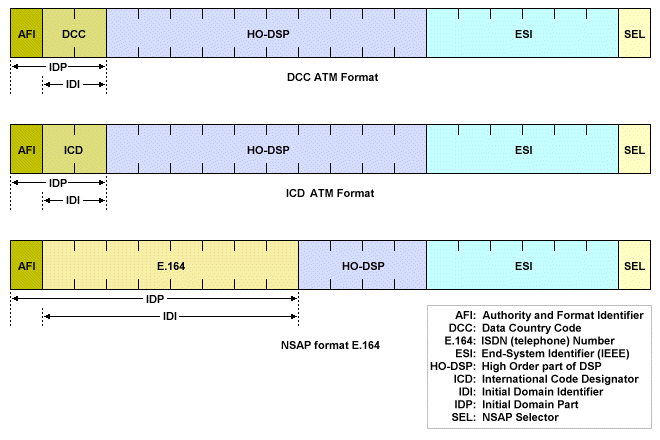
ATM address formats for private networks
NSAP-format ATM addresses consist of an authority and format identifier (AFI), an initial domain identifier (IDI), and a domain-specific part (DSP). The AFI identifies the type and format of the IDI, which in turn, identifies the address allocation and administrative authority. The DSP contains actual routing information. The first thirteen bytes uniquely identify the switch to which the ATM end system is attached, and are used by ATM switches for routing purposes. The next six bytes uniquely identify a specific ATM end system attached to the switch. The last byte identifies the target process within the destination end system. In the NSAP-format E.164 format, the IDI is an E.164 number (i.e. an ISDN telephone number). In the DCC format, the IDI is a data country code (DCC), which identifies a particular country. In the ICD format, the IDI is an international code designator (ICD) allocated by the ISO 6523 registration authority (the British Standards Institute). ICD codes identify specific international organisations. The ATM Forum recommends that organisations use either the DCC or ICD formats to create their own internal numbering scheme.
The sequence of cells in a virtual connection is preserved within each ATM switch to simplify the process of reconstructing packets or frames at their destination. Cells are routed through the ATM network using the information contained within the VPI/VCI. At each switch, the VCI and VPI together identify the virtual connection to which a cell belongs, and are used together with the incoming port number to index a routing table within the switch to determine the correct outgoing port and the new VPI/VCI values (Incoming VPI/VCI values must be translated to outgoing VPI/VCI values at every switch through which the cell passes). If a number of cells require the same output port during the same time slot, any cells that cannot be sent immediately will be placed in a queue and sent when the output port becomes available. If too many cells are queued for a particular link, some cells may be lost.
An application wishing to send data across an ATM network should advise the network of the type of data is to be sent, together with any Quality of Service (QoS) requirements. The ATM Forum has defined five service categories in order to try and match traffic characteristics and QoS requirements to network behaviour, which are described below.
Every ATM connection implements a set of parameters that describe the traffic characteristics of the source. They are listed below.
The appropriate traffic characteristics for a given connection are determined when the connection is set up, and between them define the traffic contract for the connection. The contract is intended to ensure that the requested Quality of Service is provided. Traffic shaping is implemented through the use of queuing and other measures in order to constrain data bursts, limit peak data rates, and eliminate jitter. In order to ensure that the traffic on each connection behaves and is managed according to its agreed contract, the contract may be policed by ATM switches. The switches can compare actual traffic flows against the contract. If a connection is exceeding its agreed throughput, the switch may reset the cell-loss priority (CLP) bit for offending cells, making them eligible to be discarded by any switch handling them during a period of network congestion. The Quality of Service parameters that the network strives to meet include:
LAN Emulation (LANE) is a standard defined by the ATM Forum that is intended to provide workstations, servers and other network devices with the same network connectivity over an ATM network that is normally provided by more traditional LAN technologies such as Ethernet or Token Ring. The LANE protocol defines mechanisms for emulating either an IEEE 802.3 Ethernet or an 802.5 Token Ring LAN. The service interface provided to network layer protocols is identical to that provided by IEEE 802.3 or IEEE 802.5, and data traversing the network is encapsulated in the appropriate MAC frame format. Operation of the network is transparent to the user, and the ATM network appears to behave exactly like the LAN technology it is emulating. Because the service interface presented to network layer protocols is identical to that of the corresponding MAC protocol, no modification to those protocols is required.
The ATM reference model describes the architecture of ATM and the functionality it supports. The model corresponds primarily to the first two layers (i.e. the physical and data link layers) of the OSI reference model. As well as the vertically-defined layers, the ATM model includes the following planes, which span all layers:
The ATM reference model is composed of the following layers:
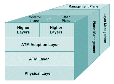
The ATM reference model
The ATM physical layer converts cells into a bit-stream, transmits and receives cells on the physical medium, tracks ATM cell boundaries, and packages cells using the framing appropriate for the physical medium. The layer is divided into the physical medium-dependent (PMD) sub-layer, and the transmission convergence (TC) sub-layer. The PMD sub-layer is responsible for the synchronisation and timing of bit streams, and specifies the correct transmission medium and connection interfaces for the physical network (e.g. SDH, SONET etc.) The TC sub-layer is responsible for maintaining and tracking cell boundaries, header error control (HEC) sequence generation (at the transmitter) and verification (at the receiver), cell-rate decoupling, (synchronising the ATM cell rate with the payload capacity of the physical transmission system) and transmission frame adaptation (packaging ATM cells in the correct frame type for the physical layer implementation).
The ATM layer is responsible for connection setup, the multiplexing or de-multiplexing of cells on different virtual connections, the translation between incoming and outgoing VPI and VCI values during switching operations, ensuring quality of service is monitored and maintained, cell header creation (or removal) as data is received from (or passed to) the adaptation layer, and flow-control.
This layer provides the interface between the ATM layer and the higher-layer protocols, and consists of two sub-layers. The Segmentation and Re-assembly (SAR) sub-layer is responsible for the segmentation of higher layer data into 48-byte payloads for outbound cells, and the reassembly of higher layer data from incoming cell payloads. The Convergence sub-layer performs functions such as message identification and time recovery. Four AAL types are recommended by the ITU-T, each of which is suited to a particular service category and connection mode. The AAL types are listed below.
ATM was developed to provide a data network for any type of application, regardless of its bandwidth requirements. Due to its complexity, and the advances made in competing technologies, it has not lived up to the original expectations of its creators, and has not gained widespread acceptance as a LAN technology. It has, however, been widely implemented in public and corporate networks. A number of telecommunications service providers have implemented ATM in the core of their wide area networks, and many DSL networks, which still run at relatively slow data rates, utilise ATM as a multiplexing service. In high-speed interconnects, ATM is often still used as a means of integrating PDH, SDH and packet-switched traffic within a common transport infrastructure.
The need to reduce queuing delays by reducing packet and frame sizes has to some extent (though not completely) gone away, due to the fact that both network data rates and switching speeds have increased dramatically since ATM was first conceived. Real-time voice and video applications are now being successfully carried over IP networks, and network performance benchmarks have routinely been surpassed, greatly reducing the incentive to deploy ATM. At the same time, interest in using ATM for carrying live video and audio has gained momentum recently, and its use in this type of environment has prompted the development of new standards for professional uncompressed audio and video data over ATM.
ATM is struggling to adapt, however, to the speed and traffic-shaping requirements of convergent network technologies, particularly with respect to the complexity associated with Segmentation and Reassembly (SAR), which is the source of a significant performance bottleneck. It is quite possible that gigabit Ethernet will supplant ATM as the technology of choice in new WAN implementations. At the same time, Multi-protocol Label Switching (MPLS) appears to be a possible contender to replace ATM as the unifying data-link layer protocol of the future, providing data-carrying services for both virtual-circuit based and packet switching network clients. The evolution of MPLS has benefited from lessons learned from ATM, and both the strengths and weaknesses of ATM have been kept in mind throughout its development.