| Author: | |
| Website: | |
| Page title: | |
| URL: | |
| Published: | |
| Last revised: | |
| Accessed: |
Recommended Standard 232 (RS-232) emerged in the 1960s as a common interface standard for data communications equipment. This data communications was often an exchange of data between a mainframe computer and a remote terminal via an analogue telephone line, and a modem was required at each end of the connection to carry out the necessary signal conversion (digital-to-analogue and vice-versa). A standard was needed to ensure reliable communication and to enable equipment produced by different manufacturers to interoperate. The standard specified signal voltages, signal timing, the function of each circuit in the interface, and a protocol for the exchange of information. It also provided the specifications for physical connectors. In the four decades since the standard first appeared, the Electronic Industries Association has made a number of modifications to the standard. The most recent version, EIA232F, was introduced in 1997. It renames some of the signal lines, and introduces some new ones, including a shield conductor.
RS-232 defines the connection between data terminal equipment (DTE) and data circuit-terminating equipment (DCE). Data terminal equipment is any end user device, such as a computer, that can be used to send data over a network. Data circuit-terminating equipment is a device that provides the interface between the DTE and the network, and is often a modem or terminal adapter. An RS-232-compatible interface was commonly used for computer serial communication (COM) ports, which were originally intended for connecting the computer to a modem. While the original RS232 standard specified 25-pin connections, many of the pins were not used in practice, and a 9-pin connection was implemented on most computers. Although the RS-232 port has now largely been superceded by USB for connecting peripheral devices to personal computers, it is still often provided to enable the connection of legacy devices. The illustration below shows the 25-pin and 9-pin DTE-to-DCE connections that would result if the EIA232 standard were strictly followed. The most commonly used signals are shown in red.
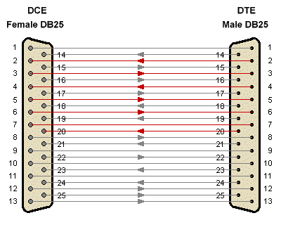
A 25-pin DTE-to-DCE connection
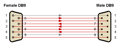
A 9-pin DTE-to-DCE connection
RS-232 allows data rates of up to 20 kbps, over cables of up to 15 metres. Control circuits are used to manage the connection between the DTE and DCE, and a special hardware circuit called a UART (Universal Asynchronous Receive/Transmit) or a USRT (Universal Synchronous Receive/Transmit) controls the serial port in a computer. Each data or control circuit operates in only one direction, and since the Transmit Data (TxD) and Receive Data (RxD) are separate circuits, the interface can operate in full duplex mode. The EIA232 standard uses negative, bipolar logic in which a negative voltage is used to represent a logic '1', and a positive voltage represents a logic '0'. A typical DTE-DCE interface setup is shown below.
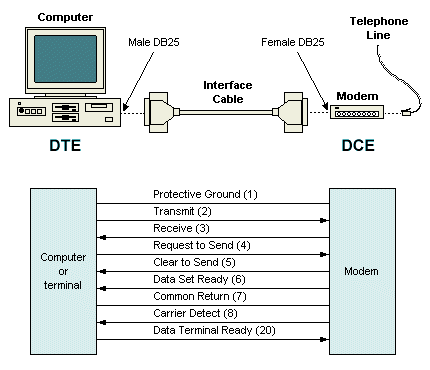
A typical DTE-DCE interface
RS-232 devices are either DTE or DCE devices. Computer terminals are usually equipped with male connectors with DTE pin functions, while modems have female connectors with DCE pin functions. Although the standard specifies twenty different signal connections, most devices use only a few of these signals, enabling the smaller 9-pin (DB9) connectors to be used. The more commonly used signals are shown in the table below.
| Signal | Description |
|---|---|
| TxD | Transmitted Data - data transmitted from the DTE to the DCE |
| RxD | Received Data - data transmitted from the DCE to the DTE |
| RTS | Request To Send - set to 0 (asserted) by the DTE to prepare the DCE to receive data |
| CTS | Clear To Send - set to 0 (asserted) by the DCE to acknowledge RTS and allow the DTE to transmit |
| DTR | Data Terminal Ready - set to 0 (asserted) by the DTE to indicate that it is ready to be connected |
| DSR | Data Set Ready - set to 0 (asserted) by the DCE to indicate an active connection |
| DCD | Data Carrier Detect - set to 0 (asserted) by the DCE when a connection has been established with a remote device |
| RI | Ring Indicator - set to 0 (asserted) by the DCE when it detects a ring signal from the telephone line |
In a standard connection between a DCE device and a DTE device, the cable used will connect the same pin numbers in each connector (a "straight-through" cable). The standard pin assignments for DB25 and DB9 connectors are given in the following tables.
| Pin | DTE (male connector) | DCE (female connector) |
|---|---|---|
| 1 | Shield | Shield |
| 2 | Transmitted Data | Received Data |
| 3 | Received Data | Transmitted Data |
| 4 | Request to Send | Clear to Send |
| 5 | Clear to send | Request to send |
| 6 | DCE Ready | DCE Ready |
| 7 | Signal Ground | Signal Ground |
| 8 | Received Line Signal Detect | Received Line Signal Detect |
| 9 | Reserved for testing | Reserved for testing |
| 10 | Reserved for testing | Reserved for testing |
| 11 | Unassigned | Unassigned |
| 12 | Second Received Line Signal Detect | Second Received Line Signal Detect |
| 13 | Second Clear to Send | Second Request to send |
| 14 | Second Transmitted Data | Second Received Data |
| 15 | Transmitter Signal Timing (DCE Source) | Transmitter Signal Timing (DCE Source) |
| 16 | Second Received Data | Second Transmitted Data |
| 17 | Receiver Signal Timing (DCE Source) | Receiver Signal Timing (DCE Source) |
| 18 | Local Loopback | Local Loopback |
| 19 | Second Request to Send | Second Clear to Send |
| 20 | DTE Ready | DTE Ready |
| 21 | Remote Loopback | Remote Loopback |
| 22 | Ring Indicator | Ring Indicator |
| 23 | Data Signal Rate Selector | Data Signal Rate Selector |
| 24 | Transmitter Signal Timing (DTE Source) | Transmitter Signal Timing (DTE Source) |
| 25 | Test Mode | Test Mode |
| Pin | DTE (male connector) | DCE (female connector) |
|---|---|---|
| 1 | Received Line Signal Detect | Received Line Signal Detect |
| 2 | Received Data | Transmitted Data |
| 3 | Transmitted Data | Received Data |
| 4 | DTE Ready | DTE Ready |
| 5 | Signal Ground | Signal Ground |
| 6 | DCE Ready | DCE Ready |
| 7 | Request to Send | Clear to Send |
| 8 | Clear to Send | Request to Send |
| 9 | DCE Ready | DCE Ready |
A connection between two DTE devices (e.g. between two computers) requires a null modem that acts as a DCE between the two devices. This is essentially a crossover cable in which a number of signal lines are cross connected (i.e. TxD to RxD, DTR to DSR, and RTS to CTS). A 9-pin null modem connection is shown below.
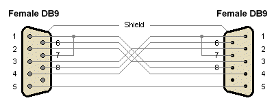
A 9-pin null modem connection
A loopback connector can be used for testing, and is simply a DB9 female connector without a cable, internally wired to reroute signals back to the sender. The connector is attached to a DTE device such as a personal computer.
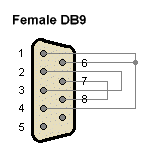
A DB9 loopback connector